
Related Manuals for MasterForce 241-0779


Summary of Contents for MasterForce 241-0779
- Page 1 7.5A Angle Grinder 241-0779 OPERATOR’S MANUAL CAUTION: To Reduce The Risk Of Injury, User Must Read And Understand Operator's Manual. Save These Instructions For Future Reference.
-
Page 2: Table Of Contents
TABLE OF CONTENTS SPECIFICATIONS Rating 120 V 60Hz Safety Symbols........Page 2 Motor 7.5 A Safety Instructions....... Page 2 Rated Speed 11000 RPM Description.......... Page 7 Assembly and Adjustment....Page 8 Wheel diameter 4 1/2” Operation..........Page 9 Arbor size 5/8”... - Page 3 c) Do not expose power tools to rain or Dress properly. Do not wear loose wet conditions. Water entering a power clothing or jewelry. Keep your hair, clothing and gloves away from tool will increase the risk of electric moving parts. Loose clothes, jewelry or shock.
- Page 4 5) Service g) Do not use a damaged accessory. Before each use inspect the accessory, a) Have your power tool serviced by a such as abrasive wheels, for chips and qualified repair person using only cracks, backing pad for cracks, tear or identical replacement parts.
-
Page 5: Safety Instructions
n) Do not run the power tool while c) Do not position your body in the area carrying it at your side. Accidental where power tool will move if kickback occurs. Kickback will propel the tool in contact with the spinning accessory could snag your clothing, pulling the accessory direction opposite to the wheel’s movement into your body. - Page 6 ADDITIONAL INSTRUCTIONS Recommended sizes of extension cords FOR SAFE OPERATION Total length of cord in Tool’s feet Cord size in A. W. a) WARNING-To reduce the risk of injury Ampere Volts G.(minimum) always wear eye protection. Everyday rating 25’ 50’ 100’...
-
Page 7: Description
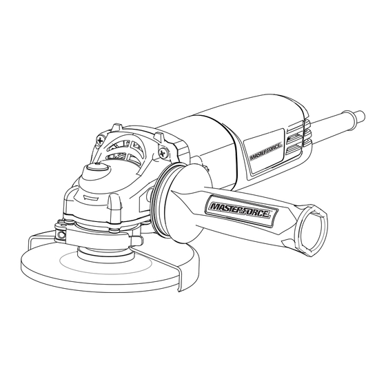
DESCRIPTION WARNING: KNOW THE ANGLE GRINDER Do not allow (Fig. 1) familiarity with the angle grinder to cause carelessness. Remember that a careless The machine is intended for grinding metal fraction of a second is sufficient enough and stone materials without using water. to inflict severe injury. -
Page 8: Assembly And Adjustment
ASSEMBLY AND ADJUSTMENT POWER SUPPLY Attaching the guard 1. Unplug the angle grinder. The power tool supply must match the 2. Make sure that the prominence on the nameplate rating. guard coincides with the groove in the gear case cover. INSTALLING SIDE HANDLE (Fig. -
Page 9: Operation
1. Unplug the angle grinder. 5. Thread the outer flange on the spindle with the flat side of the flange facing 2. Make sure that the guard (4) is securely up, making sure that the opening in the in place. wheel is positioned around the raised 3. -
Page 10: Maintenance
APPLICATION WARNING: The key to efficient operation is controlling To reduce the risk the pressure and surface contact between of injury, electric shock and damage to the grinding wheel and workpiece. the tool, before starting any work, check to determine if utility lines electricity, gas Start the angle grinder and let the motor or water supply lines are hidden in the and grinding wheel build up to full speed. -
Page 11: Standard Accessories
STANDARD ACCESSORIES 4. Avoid using solvents when cleaning plastic parts. Most plastics are susceptible to damage from various types of commercial • Side handle....1pc solvents and may be damaged by their • Wrench......1pc use. Use clean cloths and mild soap to remove dirt, dust, etc. - Page 12 NOTES page 12...
- Page 13 NOTES page 13...
- Page 14 NOTES page 14...
-
Page 15: Warranty
This MASTERFORCE brand power tool carries our famous No Hassle 3-Year Limited ® Warranty to the original purchaser. If, during normal use, this MASTERFORCE power ® tool breaks or fails due to a defect in material or workmanship within three (3) years from... - Page 16 © 2011 Menard, Inc., Eau Claire, WI 54703 05/2011...
Need help?
Do you have a question about the 241-0779 and is the answer not in the manual?
Questions and answers