
Related Manuals for MasterForce 241-0818


Summary of Contents for MasterForce 241-0818
- Page 1 8” Variable Speed Bench Grinder 241-0818 To Reduce The Risk Of Injury, User Must Read And Understand Operator’s Manual. Save These Instructions For Future Reference.
-
Page 2: Table Of Contents
TABLE OF CONTENTS Safety Symbols............Page 2 Safety Instructions...........Page 3 Carton Contents............Page 8 Specifications............Page 9 Overview................Page 10 Assembly Instructions............Page 11 Operating The Bench Grinder..........Page 13 Maintenance...............Page 15 Troubleshooting..............Page 16 Parts Explosion..............Page 17 Parts List................Page 18 Notes.................Page 20 Warranty................Page 22 Page 1... -
Page 3: Safety Symbols
SAFETY SYMBOLS THIS SYMBOL DESIGNATES THAT THIS TOOL IS LISTED BY THE INTERTEK TESTING SERVICES, TO UNITED STATES AND CANADIAN STANDARDS Page 2... -
Page 4: Safety Instructions
SAFETY INSTRUCTIONS Page 3... -
Page 5: General Safety
SAFETY INSTRUCTIONS GENERAL SAFETY 4. AVOID A DANGEROUS WORKING ENVIRONMENT. DO NOT use electrical tools in a damp environment or expose them to Operating a Bench Grinder can be rain. dangerous if safety and common sense are ignored. The operator must be familiar with 5. - Page 6 SAFETY INSTRUCTIONS 25. SECURE ALL WORK. Use clamps or 15. REMOVE ALL MAINTENANCE TOOLS jigs to secure the workpiece. This is safer than from the immediate area prior to turning “ON” attempting to hold the workpiece with your the Bench Grinder. hands.
- Page 7 SAFETY INSTRUCTIONS SPECIFIC SAFETY 5. THE BENCH GRINDER WILL PRODUCE SPARKS AND DEBRIS DURING GRINDING INSTRUCTIONS FOR BENCH OPERATIONS. GRINDERS Be sure that there are not any flammable materials in the vicinity. Frequently clean The operation of any grinder can result in grinding dust from the back of the Bench debris being thrown into your eyes, which can Grinder.
-
Page 8: Electrical Safety
SAFETY INSTRUCTIONS 17. ADDITIONAL INFORMATION regarding IMPROPER ELECTRICAL CONNECTION of the safe and proper operation of this product the equipment grounding conductor can result is available from: in risk of electric shock. The conductor with • Power Tool Institute the green insulation (with or without yellow 1300 Summer Avenue stripes) is the equipment grounding Cleveland, OH 44115-2851... -
Page 9: Carton Contents
SAFETY INSTRUCTIONS EXTENSION CORDS Use a proper extension cord. Only use cords listed by Underwriters Laboratories (UL). Other extension cords can cause a drop in Keep the extension line voltage, resulting in a loss of power and cord clear of the working area. Position overheating of tool. -
Page 10: Specifications
CARTON CONTENTS UNPACKING AND CHECKING CONTENTS CAUTION: DO NOT use acetone, gasoline or (Fig. C) lacquer thinner to remove any protective This Bench Grinder will require a minimal coatings. amount of assembly. 3. Compare the items to Figure C; verify that 1. -
Page 11: Overview
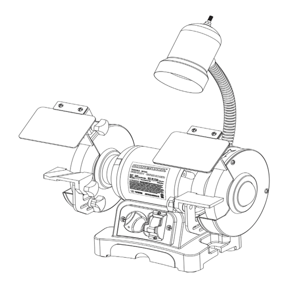
OVERVIEW FIG. D 241-0818 8” BENCH GRINDER OVERVIEW (Fig. D) A. Eyeshield Assembly, Left G. Quench Tray B. 8” Wire Wheel H. Mounting Hole (x2) C. Tool Rest Support I. 8” Grinding Wheel 60 Grit D. Tool Rest Adjustment Knobs J. -
Page 12: Assembly Instructions
ASSEMBLY INSTRUCTIONS The Bench Grinder is provided with a left and FIG. F right two piece Tool Rest. Right Tool Rest has a flat, smooth surface to lay your workpiece against. Left tool rest is used to sharpen twist drill bits. 1. - Page 13 ASSEMBLY INSTRUCTIONS EYESHIELDS (Fig. H) PERMANENT MOUNTING (Fig. I ) 1. Assemble the eyeshield (C) to the Spark Use the mounting pads on the base of the Arrestor (A) inserting carriage head screw (B) grinder to firmly attach grinder to a solid work through the Spark Arrestor and the Eyeshield surface (hardware not included).
-
Page 14: Operating The Bench Grinder
OPERATING THE BENCH GRINDER The Bench Grinder is designed for hand held grinding, sharpening, and cleaning operations. To avoid serious injury, never grind on the sides of the grinding wheels. ALWAYS WEAR EYE PROTECTION! Hot sparks are produced during grinding 7. - Page 15 OPERATING THE BENCH GRINDER USING THE WHEEL DRESSER (Fig. J) 7. Inspect the grinding wheel for any damage! FIG. J 8. The grinding wheel may now be slightly smaller in diameter after dressing. Readjust the tool rests and spark arrestors to maintain a 1/16”...
-
Page 16: Maintenance
OPERATING THE BENCH GRINDER 6. NOTE: The left hand arbor hex nut (E) is WIRE WHEEL or BUFFING WHEEL (Fig. L) left hand threaded and is loosened by rotating it clockwise. The right hand arbor hex nut is FIG. L right hand threaded and is loosened by rotating it counter-clockwise. -
Page 17: Troubleshooting
TROUBLESHOOTING TO PREVENT INJURY TO YOURSELF or damage to the Bench Grinder, turn the switch to the “OFF” position and unplug the power cord from the electrical receptacle before making any adjustments. Page 16... -
Page 18: Parts Explosion
PARTS EXPLOSION 241-0818 8” BENCH GRINDER Page 17... -
Page 19: Parts List
PARTS LIST 241-0818 8” BENCH GRINDER Part No. Description 4-0.7 x 6mm Pan Head Screw w/Washer Coolant Tray Coolant Tray Plate Circuit Board Tap Screw Cover 8-1.25 x 22mm Socket Head Bolt Switch w/ Key 3-0.5 x 10mm Pan Head Screw... - Page 20 PARTS LIST 241-0818 8” BENCH GRINDER Part No. Description Right Guard Cover 16-2.0mm Hex Nut Flange 8” Wire Wheel, 5/8” Hub 6mm Flat Washer 5-0.8 x 10mm Pan Head Screw w/Washer Right Guard w/ Label Right Toolrest Support Right Toolrest...
-
Page 21: Notes
NOTES Page 20... - Page 22 NOTES Page 21...
-
Page 23: Warranty
This MASTERFORCE¨ brand power tool carries our 90-Day Money Back Guarantee. If you are not completely satisfied with your MASTERFORCE¨ brand power tool for any reason within ninety (90) days from the date of purchase, return the tool with your original receipt to any MENARDS¨... - Page 24 © 2013 Menard, Inc., Eau Claire, WI 54703 03/2013...
Need help?
Do you have a question about the 241-0818 and is the answer not in the manual?
Questions and answers