
Related Manuals for QSC Q-SYS Core 500i


Summary of Contents for QSC Q-SYS Core 500i
- Page 1 ™ Type 2 Hardware User Manual Core 250i — Networked audio and control processor and input and output device Core 500i — Networked audio and control processor and input and output device TD-000347-00-B *TD-000347-00*...
-
Page 2: Important Safety Instructions
EXPLANATION OF TERMS AND SYMBOLS The term “WARNING!” indicates instructions regarding personal safety. If the instructions are not followed the result may be bodily injury or death. The term “CAUTION!” indicates instructions regarding possible damage to physical equipment. If these instructions are not followed, it may result in damage to the equipment that may not be covered under the warranty. -
Page 3: Fcc Statement
Damage to, or loss of any software or data residing on the product is not covered. When providing repair or replacement service, QSC will use reasonable efforts to reinstall the product’s original software confi... -
Page 4: Rohs Statement
If service is required and the original packing material is not available, ensure that the unit is adequately protected for shipment (use a strong box of appropriate size, suffi cient packing/padding material to prevent load shifting or impact damage) or call QSC’s Technical Services Group for replacement packing material and a carton. - Page 5 Plug the AC line connector into an AC outlet. The power supply on the Q-Sys Cores accepts 100 — 240 V, 50 — 60 Hz. If a different type of IEC power cord is required than that supplied with the product, consult QSC’s Technical Services Group.
- Page 6 Minimum System Requirements for Q-Sys™ Designer Q-Sys Designer is the software you use to create the designs for a Q-Sys system. After your system is designed, tested and deployed on the Core, Q-Sys designer is not required for that system to operate. Q-Sys Designer runs in a PC environment with the following minimum requirements. Software •...
-
Page 7: Quick Start Guide
1. Set up the Q-LAN network. For more information about Network Requirements see Help File Networking Topic; for a list of qualifi ed switches see “Qualifi ed Ethernet Switches” on page 13, or the QSC website (qscaudio.com). 2. Connect PC, and Core to the Q-LAN network. If you have any I/O Frames, they should be connected to the Q-LAN network at this time. - Page 8 • Q-Sys Page Stations (Optional) — Q-Sys Page Stations are a networked page station solution that connects to a Q-Sys system via Q-LAN. Q-Sys is an integrated system designed to work with QSC DataPort amplifi ers and QSC loudspeakers and other QSC products to provide system-level telemetry and control.
-
Page 9: Network Redundancy
QSC DataPort Amplifi ers QSC DataPort amplifi ers (PowerLight™, CX, PL2, DCA, and PL3) can be used in a Q-Sys system to communicate with the Q-Sys DataPort card and provide critical telemetry information and protection for both the amplifi er and any loudspeaker. With QSC loudspeaker connected to a DataPort amplifi... -
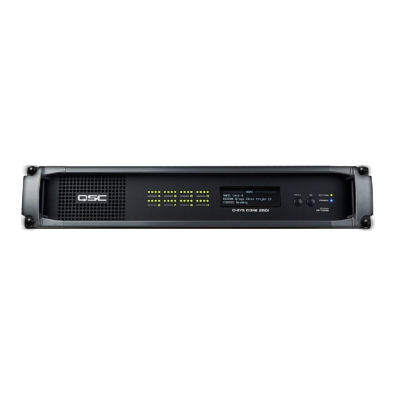
Page 10: Front Panel
NOTE: The Q-Sys hardware products are confi gured at the QSC factory per your order. At the time of order, you specify the type of Q-Sys Audio I/O Cards to be installed in the Audio I/O bays on the Q-Sys Core. In addition, Q-Sys Audio I/O Card Kits are available for fi... - Page 11 Rear Panel Core 500i — Figure 9 — 1. Eight Audio I/O Bays — accepts Q-Sys Type 2 audio I/O cards 8. Four Auxiliary Ports— USB host connectors 2. GPIO A and GPIO B Female DA-15 connectors for Q-Sys control I/O 9.
- Page 12 Q-Sys™ I/O Card Remove and Replace Procedure This procedure is for Q-Sys Type 2 I/O Cards only. Card installation should only be done by a trained and qualifi ed technician. Tools • Phillips screwdriver • ESD grounded wrist strap • 1/4” hex driver/socket (not shown) for replacing Q-Sys I/O Cards in positions C through H. —...
- Page 13 Help File in Q-Sys Designer. For more details about the following switches, refer to the manufacturers’ website. The following switches have been tested and qualify for use with a Q-Sys™ network. NOTE: Refer to the Q-Sys Online help on the QSC website for the latest list of switches. (http://www.qscaudio.com/products/software/QSys/WebHelp/) Linksys ®...
-
Page 14: Gpio Pin Assignments
Q-Sys™ GPIO Signal Specifi cations GPIO Pin Assignments DB15 Pin Signal Name Signal Type Description Relay Contact Relay - normally open Relay Contact Relay - normally closed GPIO1 Normal Current GPIO pin GPIO3 Normal Current GPIO pin POWER Power +12 V DC GPIO5 High Current GPIO pin - high current capable... - Page 15 Q-Sys Type 2 System Hardware Specifi cations Core 500i Core 250i Description System processor, control engine, and input and output device System processor, control engine, and input and output device Front Panel Controls LCD page forward momentary switch LCD page forward momentary switch Unit ID button momentary switch Unit ID button momentary switch Clear settings momentary switch...
- Page 16 Core 500i Core 250i Accessories Included 6 ft UL/CSA/IEC line cord •Rubber feet • User Manual • Software 6 ft UL/CSA/IEC line cord •Rubber feet • User Manual • Software CD • Optional audio I/O ship kit CD • Optional audio I/O ship kit 1 The maximum number of local channels a Core can have is 128 in and 128 out (64 in and 64 out).
- Page 17 DataPort Output CODP4 AES3 Input/Output CAES4 Description Four audio output channels (2 DataPorts) for connection to Four input and four output channels of AES3 digital audio DataPort equipped QSC amplifi ers Performance Dynamic Range Unweighted > 114 dB >135 dB Dynamic Range A-weighted >...
- Page 18 © 2012 QSC Audio Products, LLC. All rights reserved. QSC and the QSC logo are registered trademarks of QSC Audio Products, LLC in the U.S. Patent and Trademark office and other countries. Q-Sys and Intrinsic Correction are trademarks of QSC Audio Products, LLC. AMD is a trademark of Advanced Micro Devices, Inc. Cisco is a trademark of Cisco Systems, Inc.
Need help?
Do you have a question about the Q-SYS Core 500i and is the answer not in the manual?
Questions and answers