
Subscribe to Our Youtube Channel
Related Manuals for Julabo LC4 F


Summary of Contents for Julabo LC4 F
-
Page 1: Operating Manual
English Operating manual Temperature Controller LC4 F JULABO Labortechnik GmbH 77960 Seelbach / Germany +49 (0) 7823 / 51-0 +49 (0) 7823 / 24 91 info@julabo.de www.julabo.de 1.951.5213 01/11 19515213.DOC... - Page 2 Congratulations! You have made an excellent choice. JULABO thanks you for the trust you have placed in us. This operating manual has been designed to help you gain an understanding of the operation and possible applications of our circulators. For optimal utilization of all functions, we recommend that you thoroughly study this manual prior to beginning operation.
-
Page 3: Table Of Contents
LC4 F INDEX OPERATING MANUAL ..................4 1. INTENDED USE ....................4 1.1. Description ..................... 4 2. OPERATOR RESPONSIBILITY – SAFETY RECOMMENDATIONS .....4 2.1. Disposal......................6 2.2. EC Conformity ....................7 2.3. Warranty conditions..................7 2.4. Technical specifications.................. 8 OPERATING INSTRUCTIONS................10 3. SAFETY NOTES FOR THE USER..............10 3.1. -
Page 4: Operating Manual
The RS232C port permits modern process engineering without additional interface, directly on-line from the controller to your application equipment. The LC4 F temperature controller conforms to the safety requirements specified by DIN 12 876 as well as the guideline for first voltage range EN 61010. - Page 5 LC4 F If you have any questions concerning the operation of your unit or the information in this manual, please contact us! Contact: JULABO Labortechnik GmbH Tel. +49 (0) 7823 / 51-0 info@julabo.de Eisenbahnstraße 45 Fax +49 (0) 7823 / 24 91 www.julabo.de...
-
Page 6: Disposal
Warning label W26: Colors: yellow, black Hot surface warning. (The label is put on by JULABO) Observe the instructions in the manuals for instruments of a different make that you connect to the circulator, particularly the respective safety recommendations. Also observe the pin assignment of plugs and technical specifications of the products. -
Page 7: Ec Conformity
24 months, limited to a maximum of 10 000 working hours. To apply for this extended warranty the user must register the unit on the JULABO web site www.julabo.de, indicating the serial no. The extended warranty will apply from the date of JULABO Labortechnik GmbH’s original invoice. -
Page 8: Technical Specifications
Temperature recorder output 4 ... 20 mA / 0 ... 20 mA Programmer input 0 ... 20 mA / 0 ... 10 V Conversions for LC4 F see page 9 External alarm 24-0 V DC / max. 25 mA Interface... - Page 9 LC4 F Conversions for LC4 F: 0 ... 10 V 1 V = -50 °C, 9 V = 350 °C 0 ...20 mA 2 mA = -50 °C, 18 mA = 350 °C 4 ... 20 mA 5,6 mA = -50 °C, 18,4 mA = 350 °C...
-
Page 10: Operating Instructions
Operating instructions Operating instructions Safety notes for the user 3.1. Explanation of safety notes In addition to the safety warnings listed, warnings are posted throughout the operating manual. These warnings are designated by an exclamation mark inside an equilateral triangle. “Warning of a dangerous situation (Attention! Please follow the documentation).”... - Page 11 LC4 F protection should be set at least 25 °C below the fire point. • Set up the heating device according to the instructions prior to connection to the controller and ensure secure attachment to the bath. Danger of burning and fire! •...
-
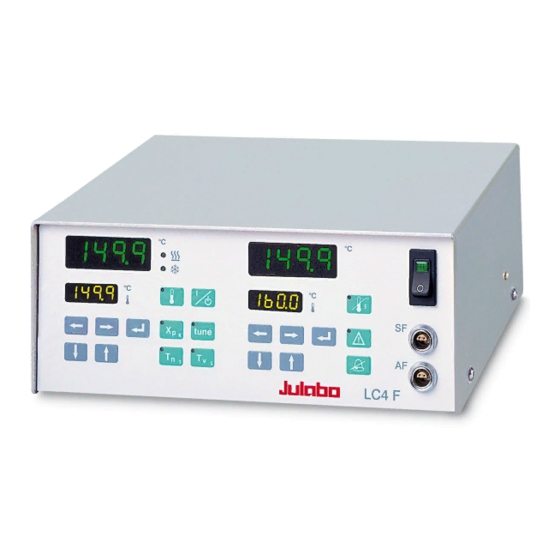
Page 12: Operating Controls And Functional Elements
Operating controls and functional elements Operating controls and functional elements Rear view Mains power switch, illuminated Keypad: working area Start / stop key Working temperature setpoint Control parameter Xp (proportional range) Control parameter Tn (resetting time) Control parameter Tv (lead time) Tune key: determining the control parameters... - Page 13 LC4 F Keypad: safety area Safety temperature setpoint Key- Indicator light – alarm Reset safety temperature alarm Key- Silent alarm signal Indication of : A = MULTI-DISPLAY (LED) S = Temperature of safety sensor SF Indication of: A = Working temperature setpoint...
-
Page 14: Operating Procedures
Operating procedures Operating procedures 5.1. Installation • The unit should be set up at a dry location. • Place the unit in an upright position and do not obstruct the ventilation. • A wall distance of at least 10 cm must be maintained for ventilation, allowing internal heat to be conducted away from the unit. -
Page 15: Connecting A Heating Device
LC4 F 5.3. Connecting a heating device Caution: Set up the heating device according to the instructions or securely fix the unit in the bath tank using appropriate means. Danger of burning and fire! Connect the power plug to the grounded mains socket (16) on the rear of the controller. -
Page 16: Applications
Operating procedures 5.5. Applications Directly heated bath liquid: • The bath liquid is directly heated via the heating device. • Working and safety sensors must both be immersed in the bath liquid.. • Whenever countercooling is necessary (in case of temperature application near the ambient temperature), cooling in the bath is performed through a cooling coil connected to a solenoid valve and the MVS controller. - Page 17 LC4 F Indirectly heated bath liquid: • The bath liquid is indirectly heated. • Working and safety sensors must both be immersed in the bath liquid.
-
Page 18: Switching On / Start - Stop
Operating procedures 5.6. Switching on / Start - Stop Switching on: Turn on the mains power switch. The unit performs a self-test. A signal sounds, and all segments of the 4-digit displays as well as all indicator lights will illuminate. Then the software version (example: n 0.0) and the model description "LC 4"... -
Page 19: Setting The Temperature
LC4 F The unit also enters the safe operating state "OFF" or "r OFF" after a mains power interruptance. The temperature values entered via the keypad remain in memory. With the controller in keypad control mode, press the start/stop key to restart operation. -
Page 20: Self-Tuning The Pid-Control Parameters Xp, Tn Und Tv
Operating procedures 5.8. Self-tuning the PID-control parameters Xp, Tn und Tv The parameters Xp, Tn and Tv are permanently and automatically determined and stored by means of the self- tuning facility. • Press the key and start the controller by pressing the start/stop key. -
Page 21: Setting The Pid Control Parameters Xp, Tn And Tv
LC4 F 5.9. Setting the PID control parameters Xp, Tn and Tv If the self-tuning function is switched off, the controller will use the stored values as the control parameters. This value can be adjusted manually. Setting the Xp (proportional range) 1. - Page 22 Operating procedures Setting the Tv (lead time) 1. Press the key The indicator light blinks and the effective value for Tv appears on the MULTI-DISPLAY (LED). 2. Follow the instructions 3. for 4. (example: 14 s). Setting range for Tv: 0 to 1000 s. With Tv set to 0 eingestellt, the differential part of the controller is deactivated (use of a P or PI type controller).
-
Page 23: Optimization Instructions For The Pid Control Parameters
LC4 F 5.9.1. Optimization instructions for the PID control parameters The heat-up curve reveals inappropriate control settings. optimum setting Inappropriate settings may produce the following heat- up curves: Xp too low Tv/Tn too low Xp or Tv too high Tv/Tn or Xp too high... -
Page 24: Setting The Safety Temperature (With Shutdown Function)
Operating procedures 5.10. Setting the safety temperature (with shutdown function) (excess temperature protection) This safety installation is independent of the control circuit. As soon as this safety installation is triggered, a complete shutdown of the connected heating device is effected. Setting the safety temperature: 1. - Page 25 LC4 F To stop the safety temperature alarm: 1. Press the key to silence the alarm. 2. Determine the cause of the alarm. Possible causes: • The safety temperature setpoint is set lower than the working temperature setpoint. • The working sensor is not connected to the temperature control medium.
-
Page 26: Menu Functions
Menu functions Menu functions The setting of the parameters and the setpoints of the controller can be dialed up at any time through the menu in the working area and safety area of the keypad. The ATC menu option, which is in the safety area of the keypad, can only be used for calibrating the safety sensor. -
Page 27: Temperature Recorder Output - Ao
LC4 F • After exiting the menu level, the corrected value (example: 36.7 °C) is indicated on the MULTI-DISPLAY (LED). Recommendation: In case a calibrated temperature measuring instrument is used, the ATC function allows the controller to be used as testing instrument according to ISO 9000. -
Page 28: Programmer Input - Ep
Menu functions 6.3. Programmer input - EP - The programmer input „E-PROG“ can be connected to the output of an external programmer used in the application This arrangement is connected with a software and hardware setting. Software setting under menu option EP Factory setting: 0 0 = electrical power output 4 ... - Page 29 LC4 F 0 ... 10 V 1 V = -50 °C, 9 V = 350 °C 0 ...20 mA 2 mA = -50 °C, 18 mA = 350 °C 4 ... 20 mA 5,6 mA = -50 °C, 18,4 mA = 350 °C Change-over to the range 0 ...
- Page 30 Menu functions Setting the lower value • With the edit keys change the menu function from “ EPL0” to " EPL1" and then press enter • Using the cursor keys and the edit keys set the upper limit (example: 0.0 °C) and then press enter Change-over to the factory setting range 4 ...
- Page 31 LC4 F Other ranges can be chosen freely Example in Diagram: EPH0 = 160.0 °C EPL0 = 20.0 °C Resulting increases: 10 °C/mA 20 °C/V Setting the upper value • With the edit keys change the menu function from “...
-
Page 32: Interface Parameters H - P - Br - R
Menu functions 6.5. Interface parameters H - P - br - r - Whenever the parameter setting of the controller is not conform to those of the connected personal computer, a modification is necessary. Factory setting of the RS232 interface: Baudrate: 4800 Bauds Parity:... -
Page 33: Controlling The Heater Capacity - H
6.7. Active countercooling - Pc - For applications near the ambient temperature, countercooling might become necessary. For this purpose, connect the JULABO MVS solenoid valve controller to the / alarm socket (application example see page 16). The supply of a cooling pulse "Pc" must be activated on the controller. -
Page 34: Warning Functions - Ll / Hl
Menu functions 6.8. Warning functions - LL / HL - )) )) )) More protection for your samples in the bath! An audible signal sounds in intervals when the actual temperature value exceeds one of the set limits (patented). Setting the lower limit •... -
Page 35: Troubleshooting Guide / Error Messages
If the error reappears, contact an authorized JULABO service station. If necessary have the unit checked by a JULABO service technician. Mains fuses • The mains fuses on the rear of the unit may easily be exchanged as shown on the left. -
Page 36: Electrical Connections
Electrical connections Electrical connections Notice: Use shielded cables only. The shield of the connecting cable is electrically connected to the plug housing. Connectors for temperature sensors(11 + 12) SF + AF Pin assignment: Pin 1 Current + Pin 2 Voltage + Pin 3 Voltage - Shield... - Page 37 LC4 F / ALARM - connector The " ALARM" connector may be used as output for alarm messages. Circuit: Operation = relay powered Alarm = relay not powered Pin assignment: Pin 1: +24 V (max. current 25 mA) Pin 2: 0 V...
- Page 38 Electrical connections Caution: Improper maintenance or repair can result in electric shock or damage to the unit. Service and repair work may be performed only by authorized electricians. Always turn off the unit and disconnect the mains cable from the power source before performing any service or maintenance procedures, or before moving the unit.
-
Page 39: Remote Control
LC4 F Remote control 9.1. Communication with a PC or a superordinated data system Suitable terminal programs for communicating with a PC are: • MS-Windows - Terminal.EXE (included with MS-Windows). If the controller is put into remote control mode via the configuration level, the display will read "r OFF"... -
Page 40: List Of Commands
Remote control 9.2. List of commands Command Parameter Description version none Number of software version (V X.xx) status none Status message, error message (see page 40) out_mode_05 Stop the controller = r OFF out_mode_05 Start the controller out_sp_00 xxx.x Set working temperature in_sp_00 none Ask for working temperature... -
Page 41: Error Messages
LC4 F 9.4. Error messages Error messages Description -03 EXCESS TEMPERATURE WARNING High temperature warning "HL". -04 LOW TEMPERATURE WARNING Low temperature warning "LL". -05 TEMPERATURE MEASUREMENT Error in measuring system. ALARM -07 I 2 C-BUS WRITE ERROR Internal errors... -
Page 42: Cleaning / Repairing The Unit
Periodic maintenance is not required. Clean the outside of the unit using a wet cloth and low surface tension water. Before asking for a service technician or returning a JULABO Repairs: instrument for repair, please contact an authorized JULABO service station.
Need help?
Do you have a question about the LC4 F and is the answer not in the manual?
Questions and answers