Table of Contents
Advertisement
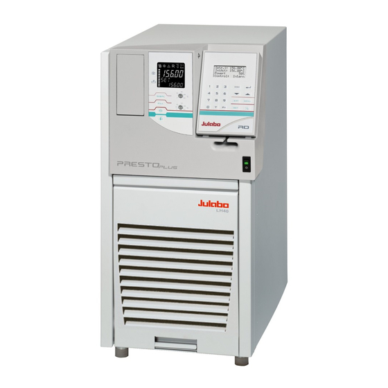
Operating Manual
High Dynamic Temperature System
with integrated programmer
Presto
LH 40
Version: V45D-01
Printed in Germany
Changes without prior notification reserved
1.951.2761BE4
03/07
19512761.doc
®
Innovative Temperature Technology
JULABO Labortechnik GmbH
77960 Seelbach / Germany
+49 (0) 7823 / 51-0
+49 (0) 7823 / 24 91
info@julabo.de
www.julabo.de
Print date: 13.06.07
Advertisement
Table of Contents

Subscribe to Our Youtube Channel
Related Manuals for Julabo LH 40


Summary of Contents for Julabo LH 40
-
Page 1: Operating Manual
Operating Manual High Dynamic Temperature System with integrated programmer ® Presto LH 40 Innovative Temperature Technology Version: V45D-01 JULABO Labortechnik GmbH 77960 Seelbach / Germany +49 (0) 7823 / 51-0 Printed in Germany +49 (0) 7823 / 24 91 Changes without prior notification reserved ... - Page 2 Congratulations! You have made an excellent choice. JULABO thanks you for the trust you have placed in us. This operating manual has been designed to help you gain an understanding of the principles of operating and possibilities of our instruments. For optimum utilization of all functions, we recommend that you thoroughly study this manual prior to beginning operation.
-
Page 3: Table Of Contents
® Presto TABLE OF CONTENTS OPERATING CONTROLS AND FUNCTIONAL ELEMENTS .......4 QUALITY MANAGEMENT SYSTEM..............8 UNPACKING AND CHECKING................8 DESCRIPTION.....................8 ® 4.1. The Presto principle with closed external system ..........9 PREPARATIONS ....................10 5.1. Bath liquids ......................10 5.2. Tubing........................13 5.3. Set up ........................14 5.4. -
Page 4: Operating Controls And Functional Elements
Operating controls and functional elements Operating controls and functional elements Front view Mains power switch, illuminated Local operating board Socket board Removable control module Filling funnel (hinged) Handle (foldaway) Venting grid, removable Drain with drain port Local operating board VFD-Info-Display Header: Control indicators see section 2.2 Line 1: Actual value... - Page 5 ® Presto Control indicators in the header: Heating / Cooling / Alarm / Remote control Temperature indication Internal or External actual value Temperature indication in °C or °F Display for the adjusted pump pressure stage (five grades), adjustable via the key Liquid level display (five grades) for the reservoir.
- Page 6 Operating controls and functional elements Control module RD DIALOG-DISPLAY (LCD) Standard indication Line 1: Setpoint in °C Setp: 120.00°C Line 2: Internal actual value in °C IntAct 21.00°C Line 3: External actual value in °C ExtAct: 20.00°C Line 4: Control type: internal / external control Control: Intern Indicating messages (e.
- Page 7 ® Presto Rear Control connector 230 V / max. 0.1 A 4 Mains circuit breakers (resettable) 16 A F1 and F3 Compressor F2 and F4 Heater, Pump Mains power cable with plug Pump connectors Return Feed M16x1 13 + 14 Overflow connector M16x1 Connector for expansion vessel M16x1...
-
Page 8: Quality Management System
Quality Management System Quality Management System Quality Management System The JULABO Quality Management System: Development, production and distribution of temperature application ISO 9001 instruments for research and industries conform to the requirements according 2000 to DIN EN ISO 9001:2000. Certificate Registration No. 01 100044846 Unpacking and checking Unpack the instrument and accessories and check for damages incurred during transit. -
Page 9: The Presto Principle With Closed External System
® Presto ® 4.1. The Presto principle with closed external system (e.g. double-sided glass vessel). Operating: The operation of the temperature system and the indication is effected via the local control panel (2) and the removable operating device RD(4). Filling : First connect the external consumer. -
Page 10: Preparations
Caution: Please contact JULABO before using other than recommended bath liquids. JULABO takes no responsibility for damages caused by the selection of an unsuitable bath liquid. Unsuitable bath liquids are liquids which e.g. - Page 11 ® Presto Important notice concerning the recommended bath liquids: Bath liquids with a range of application above the fire point ? This temperature system is mainly operated in a closed external system (loop circuit). The contact of the bath liquid with atmospheric oxygen only takes place in the internal reservoir, which is not located directly in the termperature circuit.
- Page 12 Preparations Diagram 1: JULABO Thermal oils Change in volume in dependence on the temperature of bath liquid. Examples: Rough estimate for LH45 (2,6 liters) with an external closed system (2,4 liters). Example A: Filling quantity at ambient temperature 5 liters Intended working temperature range -40 °C bis +250 °C...
-
Page 13: Tubing
® Presto 5.2. Tubing Recommended tubing: Metal tubing, triple insulated, M16x1, Temperature range -100 °C ... +350 °C Order No. Length 8 930 209 0.5 m 8 930 210 1.0 m 8 930 211 1.5 m 8 930 214 3.0 m Metal tubing, insulated, M16x1, Temperature range -50 °C ... -
Page 14: Set Up
(loop circuits). The temperature application of external, open systems is also possible. However, this requires a series of special measures which Julabo cannot influence like e.g. the protection of the bath liquid from environmental influences such as oxygen and air humidity. - Page 15 ® Presto Important: Connect a piece of tubing to the overflow connector (15) and drain into a suitable vessel. (M16x1 / wrench 19 mm), which always has to be placed lower thant the exit „Overflow“. If required, the connector (16) may be ...
-
Page 16: Power Connection
2,6 ... 4,0 - in the heat exchanger - in the internal reservoir Example: LH 40 Indication max: 3,2 liters Recommendation: For filling, use for example an approx. 2 liters measuring jug. Select the bath liquid suitable for the temperature application task. -
Page 17: Filling Of External, Closed Systems
® Presto 5.6.1. Filling of external, closed systems Section 1 ALARM Connect the unit to a mains power socket (see page 16) and turn on the unit with the mains power switch (1). CODE 14 During the self-test all segments of the VFD-Info-Display, all control indicators and the DIALOG-DISPLAY light up. - Page 18 Preparations Adjusting Mode: Notice concerning the filling The temperature system was emptied last, therefore the menu option >Mode< now still stands on >drain<. In the configuration of this unit the >Mode< >fill< means the same as >drain< and therefore does not have to be adjusted. Explanation of terms: ®...
-
Page 19: Degasifying
® Presto 5.7. Degasifying If the temperature system is operated in a closed, external consumer, >Mode: sys close<, an automatic degasifying is carried out after the start.. During the degasifying unwelcome components of the bath liquid are are drawn off . Examples: ... -
Page 20: Draining
Preparations 5.8. Draining Notice: Exercise caution when emptying hot bath liquids! Store and dispose the used bath liquid according to the laws for environmental protection. Draining Turn on the temperature system with the mains power switch or 20.00 press the stop key to make the unit enter the STOP- x.xx MODE. -
Page 21: Operating Procedures
Switching on: The unit is operated by pressing the mains power switch (1). The integrated pilot lamp illuminates. JULABO P R E S T O During the self-test all segments of the VFD-Info-Display, all control indicators and the DIALOG-DISPLAY light up. -
Page 22: Manual Operation
Manual operation Manual operation 7.1. Start - Stop Start: Setp.: 20.00°C IntAct 21.00°C ExtAct: --.--°C Press the start/stop key Control: Intern The actual bath temperature is displayed. For approx. 3 seconds the VFD-Info-Display shows the adjusted >Mode< . 20.00 Adjustment >... -
Page 23: Direct Setting Of The Working Temperature
® Presto 7.2. Direct setting of the working temperature This setting may be carried out with the temperature system Setp.: 20.00°C being in operating state Start or Stop! IntAct 21.00°C ExtAct: --.--°C The value previously set appears on the DIALOG- ... -
Page 24: Warning Functions
Manual operation 7.3.2. Warning functions The high and low temperature warning functions accompany the working temperature value. An audible signal sounds in intervals when the actual temperature exceeds one of the set limits (patented). The corresponding message appears in line 4 on the DIALOG-DISPLAY (LCD). -
Page 25: Setting The Pump Pressure Stage
® Presto 7.3.3. Setting the pump pressure stage The pressure of the circulation pump is adjustable in five grades. After setting, the VFD-Info-Display indicates the corresponding value. >St.Pump: Setting the pump pressure stage Setp.: 120.00°C Setting in line 4. Overt.:130.00°C The value previously set appears on the DIALOG- Subtmp:110.00°C... -
Page 26: Setting The Safety Temperature (With Shutdown Function)
Manual operation 7.4. Setting the safety temperature (with shutdown function) This safety feature functions independent of the regulator TANK 150 circuit. When the temperature of the bath liquid has reached the safety temperature, a complete shutdown of the heater and pump is effected. - Page 27 ® Presto Press enter to quit the audible signal. After eliminating the malfunction, press the mains power switch off and on again to cancel the alarm state. Warning: Recommendation for external, closed systems: (see page 9) Set the safety temperature >TANK< 15 °C above the working temperature setpoint.
-
Page 28: Internal / External Control
Menu functions 7.5. Internal / external control The temperature system offers the possibility of internal temperature control in the internal bath or external control directly in an external system. Setup for external control: ® Connect a Pt100 sensor to the socket "EXT" of the Presto temperature system, if necessary perform a calibration using ext. - Page 29 ® Presto...
-
Page 30: Configuration
Menu functions 8.1. Configuration By means of the configuration functions, operation of the instrument can be optimized for the current application. >Configuration Controlparam. Profile Start Configuration Int.Programmer Identif. xxxxx Press enter to select the configuration submenu. Inputs/Outputs Setpoint xxxxx Limits Autostart Interface... - Page 31 >Autostart Note: The temperature system has been configured and supplied by JULABO according to N.A.M.U.R. recommendations. This means for the start mode, that the unit must enter a safe operating state after a power failure (non-automatic start mode). This safe operating state is indicated by "OFF", resp.
- Page 32 Menu functions Should such a safety standard not be required, the AUTOSTART function (automatic start mode) may be activated, thus allowing the start of the instrument directly by pressing the mains power switch or using a timer. Possible parameters: on - AUTOSTART on off - AUTOSTART off Warning For supervised or unsupervised operation with the AUTOSTART function, avoid...
-
Page 33: Control Parameters
® Presto 8.2. Control parameters When performing an identification for the controlled system (temperature applications system) (see page 30), the control parameters Xp, Tn, Tv and Xpu will be automatically determined and stored. Each parameter may be manually set via the keypad if necessary, to allow optimum control performance. - Page 34 Menu functions >DynInt< - Dynamics standard °C This parameter affects the march of temperature only in temp. stability case of internal control (see page 28) aperiod. setpoint Adjustable parameter: standard The temperature rises quicker, however can overshoot up to 5 %. If a ramp is standard defined, the march of temperature often °C...
-
Page 35: Start Of A Profile
® Presto 8.3. Start of a profile The start menu of the integrated programmer allows calling up and defined starting of one of six previously stored temperature profiles. The profiles are started manually or via the integrated timer. There are two possibilities for manually starting a program: 1. - Page 36 Menu functions When selecting the parameter time, a new menu level is called up for entry of the start time. A flashing segment indicates that a start time needs to be entered. Example: hour.min 6:00 h hour.min Start time Day.Mon day and month Year...
-
Page 37: Interrupting A Profile
® Presto 8.3.1. Interrupting a profile Interrupting a profile: Press the start/stop key to interrupt or continue a profile. The setpoint and time period set for the corresponding section are thus stopped at the values presently achieved. The instrument is put on hold and the message "pause" flashes on the DIALOG DISPLAY (LCD). -
Page 38: Integrated Programmer
Menu functions 8.4. Integrated programmer The integrated programmer allows any desired temperature program sequences to be realized. Such a temperature sequence is called profile. A profile consists of individual sections defined by duration (t:) and target temperature. Target temperature is the setpoint (T:), that is achieved at the end of a section. - Page 39 ® Presto Edit Int.Programmer >Edit Compile profiles: Delete Set Clock >Edit Profile: 1 A flashing segment indicates that a number needs to be Step: Setp: 100.00°C entered. Time[h.m] 01:05 Under submenu "Edit Profile" enter a profile number. Six profiles may be stored (nos. 0 to 5). Examples: ...
- Page 40 Menu functions Delete A flashing segment indicates that the respective profile number needs to be entered in which one or more consecutive sections are to be deleted. In lines 2 and 3 of the DIALOG DISPLAY (LCD) enter the numbers of the sections to be deleted.
-
Page 41: Analog Inputs/Outputs
® Presto 8.5. Analog inputs/outputs This submenu enables setting of the input and output values for the programmer input and the temperature recorder outputs of socket REG+E-PROG (21). Press enter to select the inputs/outputs submenu. Use the up/down cursor keys to select the desired option and press enter to open. - Page 42 Menu functions Examples: lowest temperature value: 10 °C highest temperature value 210 °C Fig. shows 200 C scaled to paper width rise: 50 mV/°C lowest temperature value: 197 °C highest temperature value: 202 °C Fig. shows 5 C scaled to paper width rise: 2000 mV/°C EPROG - Input This input is necessary when the nominal value is to be...
- Page 43 ® Presto This EPROG input enables the use of different voltage and current values as program parameters. "L Value" - Setting the LOW value: 1) Adjust and set the lowest desired value on the voltage or current source resp. (Example A: 1 V). 2) Assign a lower temperature threshold value to this adjusted voltage/current value by pressing the appropriate buttons on the keypad of the instrument (Example A: 20 C...
-
Page 44: Limits
Menu functions 8.6. Limits The limits IntMax and IntMin are only valid under external Int.Programmer control (see 7.5. Internal / external control). They restrict Inputs/Outputs Limits the temperature of the internal bath to the desired Interface maximum/minimum, also if the controller would require a Temp.Sensor Limits higher/lower temperature for the external system. -
Page 45: Sensors
® Presto 8.8. Sensors ATC - Absolute Temperature Calibration Select the submenu "Temp.Sensor" with enter Select the desired option with the up/down cursor keys A flashing digit indicates that a value needs to be entered i.e. set. ATC Int: internal sensor ATC Ext: external sensor... -
Page 46: Pump
Menu functions 8.9. Pump In this submenu the circulation pump can be turned on separately, without heating element or cooling unit. The menu option „Modus“ refers to the filling valve and the ventilation valve. Depending on the operating status (drain / fill Limits Interface / sys open / sys close) the valves are switched off... -
Page 47: Troubleshooting Guide / Error Messages
CODE 14 Defect temperature sensor in refrigeration circuit. CODE 02 Repair by authorized JULABO service personnel. Cable of the working temperature sensor interrupted or short- CODE 05 circuited. Defect of the working or safety temperature sensor. - Page 48 After eliminating the malfunction, press the mains power switch off and on again to cancel the alarm state. If the unit cannot be returned to operation, contact an authorized JULABO service station. Disturbances that are not indicated. Pump motor overload protection ...
-
Page 49: Safety Recommendations
® Presto 10. Safety recommendations Follow the safety recommendations to prevent damage to persons or property. Further, the valid safety instructions for working places must be followed. See also chapter 16. Responsibility of the operator Only connect the unit to a power socket with earthing contact (PE – protective earth)! ... -
Page 50: Electrical Connections
Electrical connections 11. Electrical connections RS232/RS485 serial interface (3.5) This port can be used to connect a computer with an RS232 or RS485 cable for remote control of the temperature system. SERIAL Pin assignments: RS232 Pin 2 Receive Data Pin 3 Transmit Data Pin 5 0 VD... - Page 51 ® Presto Programmer input / temperature recorder output (3.1) Analog inputs / outputs see page 41 Signal 1 Voltage output Channel 1 0 ... 10 V 2 Voltage output Channel 2 0 ... 10 V 3 GND for outputs REG+E-PROG 4 Programmer input EPROG 0 to 10 V / 0 to 20 mA...
- Page 52 Electrical connections STAND-BY input (3.2) (for external emergency switch-off) Pin assignment: Signal not connected 5 V / DC Use shielded cables only. Activate the stand-by input: Under menu item Stand-by, set the parameter to "yes" (see page 32). Connect an external contact 'AK' (e.g. for emergency switch-off) or an alarm contact of the superordinated system.
-
Page 53: Remote Control
® Presto Connector for removable control module RD (3.6) Extension cable for operating device RD: Order No. 8 980 126 2 m long Order No. 8 980 127 5 m long Control connector (10) Output voltage is applied when the unit runs, for example after pressing the start/stop key Output voltage: 230 V... - Page 54 Remote control If the temperature system is put into remote control mode via the configuration level, the display will read "R -OFF-" = REMOTE STOP. In general, the computer (master) sends commands to the instrument (slave). The instrument sends data (including error messages) only when the computer sends a query.
-
Page 55: List Of Commands
® Presto 12.3. List of commands When the RS485 interface is used, the instrument address stands in front of each command (Axxx_). in commands: Asking for parameters or temperature values to be displayed. Command Parameter Response of instrument version none Number of software version (V X.xx) status none... - Page 56 Remote control Command Parameter Response of instrument none Temperature system in Stop/Start condition: in_mode_05 0 = Stop 1 = Start none Adjusted control dynamics in_mode_08 0 = aperiodic 1 = standard in_par_01 none Time constant of the external bath. none Internal slope.
- Page 57 ® Presto out commands: Setting parameters or temperature values. Command Parameter Response of instrument Use working temperature out_mode_01 No identification. out_mode_02 Temperature control by using the stored parameters. out_mode_02 Single identification of controlled system after the next start. Continual identification of controlled system whenever a new out_mode_02 setpoint is to be reached.
-
Page 58: Status Messages / Error Messages
Remote control Command Parameter Response of instrument Tn control parameter of the cascade controller. out_par_11 out_par_12 Tv control parameter of the cascade controller. out _par_13 Maximum internal temperature of the cascade controller. out _par_14 Minimum internal temperature of the cascade controller. 12.4. - Page 59 ® Presto Error messages Description Defect temperature sensor in refrigeration -02 REFRIGERATOR ALARM circuit. -03 EXCESS TEMPERATURE WARNING High temperature warning " ". -04 LOW TEMPERATURE WARNING Low temperature warning " ". -05 WORKING SENSOR ALARM Working temperature sensor short-circuited or interrupted.
-
Page 60: Maintaining The Cooling Performance
Maintaining the cooling performance 13. Maintaining the cooling performance Air-cooling: To maintain the full cooling performance, clean the condenser from time to time. Switch off the unit, disconnect mains power cable. Hold the venting grid, pull out and remove. ... -
Page 61: Cleaning The Unit
Clean the outside of the unit using a wet cloth and low surface tension water (e.g., soap suds). Before applying a cleaning or decontamination method different from the one recommended by JULABO, the user has to make sure with the manufacturer, that the planned method does not damage the unit. Cleaning the inside: If you change the bath liquid or want to use a different one, carefully clean the parts in contact with the bath liquid. - Page 62 Cleaning the unit Cleaning is performed in three steps. First rinse the internal reservoir, then the remaining parts of the instrument. As third step, carefully remove the cleaning liquid. 1. Cleaning the internal reservoir: Switch off the unit with the mains switch! Thus both valves "Fill"...
-
Page 63: Responsibility Of The Operator
During transport the unit has to stand upright. Mark the packing correspondingly. When returning a unit, take care of careful and adequate packing. JULABO is not responsible for damages that might occur from insufficient packing. JULABO reserves the right to carry out technical modifications with repairs for... -
Page 64: Technical Specifications
Technical specifications 18. Technical specifications Working temperature range °C -40 ... 250 Temperature stability °C ±0.01 ... ±0.05 Cooling capacity °C 200 / 20 -20 (bath liquid: Thermal / Ethanol) 1.5 / 1.0 0.4 0.05 Cooling compressor 1-stage Refrigerant R404A Heater wattage Watts 1800... - Page 65 ® Presto Safety installations according to IEC 61010-2-010: Excess temperature protection >TANK< adjustable from 0 °C ... 320 °C Excess temperature protection >RES< adjustable from 0 °C ... 220 °C Low level protection float switch Liquid level display optical, 5-graded Classification according to DIN 12876-1 class III FL Supplementary safety installations...
-
Page 66: Ec Declaration Of Conformity
EN 61010 refrigerated and heating circulators – safety and environmental – conscious requirements outlined by EN 378 Julabo Labortechnik GmbH Eisenbahnstr. 45 D-77960 Seelbach / Germany G. Juchheim, Managing Director... -
Page 67: Warranty Conditions
24 months, limited to a maximum of 10 000 working hours. To apply for this extended warranty the user must register the unit on the JULABO web site www.julabo.de, indicating the serial no. The extended warranty will apply from the date of JULABO Labortechnik GmbH’s original invoice.
Need help?
Do you have a question about the LH 40 and is the answer not in the manual?
Questions and answers