Table of Contents
Advertisement
I0-231
EFFICIENCY
RATING
CERTIFIED
ama
INSTALLATION & OPERATING
INSTRUCTIONS
for GMNTE
CONDENSING GAS FURNACE
WARNING
THIS FURNACE IS DESIGN CERTIFIED FOR IN-
STALLATION IN BUILDINGS CONSTRUCTED ON
SITE ONLY.
WARNING
DO NOT USE THIS FURNACE IF ANY PART HAS
BEEN UNDERWATER. IMMEDIATELY CALL A
QUALIFIED SERVICE TECHNICIAN TO INSPECT
THE FURNACE AND TO REPLACE ANY PART OF
THE CONTROL SYSTEM AND ANY GAS CON-
TROL THAT HAS BEEN UNDERWATER.
All information contained herein is subject to change without notice.
Goodman Manufacturing Company, L.P.
2550 North Loop West, Suite 400, Houston, TX 77092
www.goodmanmfg.com
2003 Goodman Manufacturing Company, L.P.
©
(CATEGORY IV)
®
C
US
6/03
Advertisement
Table of Contents

Related Manuals for Goodman GMNTE


Summary of Contents for Goodman GMNTE
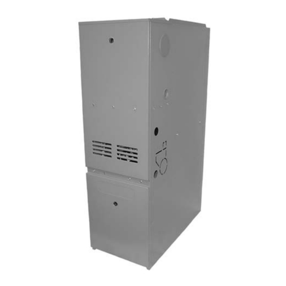
- Page 1 EFFICIENCY RATING ® CERTIFIED INSTALLATION & OPERATING INSTRUCTIONS for GMNTE CONDENSING GAS FURNACE (CATEGORY IV) WARNING THIS FURNACE IS DESIGN CERTIFIED FOR IN- STALLATION IN BUILDINGS CONSTRUCTED ON SITE ONLY. WARNING DO NOT USE THIS FURNACE IF ANY PART HAS BEEN UNDERWATER.
-
Page 2: Table Of Contents
INDEX The major parts groups are as follows: Warnings & General Information ......2 BLOWER ASSEMBLY Motor Clearances, Location ..........4 Blower Housing Blower wheel Combustion Air ............4 Misc. sheetmetal items Venting ..............6 Inductor HEAT EXCHANGER Condensate Drains ..........9 Heat exchanger sections Gas Piping ............ - Page 3 LIQUID PETROLEUM GAS BURNING APPLIANCE IN A PIT, BASEMENT, OR SIMILAR LOCATION. L.P., A HEAVIER THAN The GMNTE series furnace can be installed as an upflow, AIR GAS, CAN COLLECT IN LOW AREAS AND MAY NOT DIS- downflow or horizontal furnace. It can also be installed as a PERSE NATURALLY.
-
Page 4: Clearances, Location
1/2 psig (3.5 kPa). The GMNTE furnace can be installed either as a Direct Vent (2 pipe) or a Non-Direct Vent (1 pipe) appliance. If MIN. - Page 5 Direct Vent Combustion Air. As shown in the following If the optional concentric vent kit (CVK-00) is used follow illustration, the combustion air pipe is to originate at the the instructions provided with this accessory. furnace’s cabinet and terminate outside of the building. The diameter of the PVC combustion air pipe depends Non-Direct Vent Combustion Air.
-
Page 6: Venting
90° is preferred. Do not count the termination as an elbow. 3. The following installations may require OUTDOOR AIR for combustion, due to chemical exposures; Model Vent Pipe Comb. Air • GMNTE Diameter Pipe Diameter Commercial buildings • Buildings with indoor pools 060-3 3"... - Page 7 • THE VENT AND COMBUSTION AIR SUPPLY PIPES NON-DIRECT VENT INSTALLATION - DO NOT MUST BE INSPECTED ANNUALLY. locate the vent terminal less than (4) feet below or (4) feet horizontally from any door, window or gravity Visually check the vent terminal and combustion air supply air inlet into any building.
-
Page 8: Joining Pipe And Fittings
GOODMAN. recommended for proper drainage. DO NOT install the vent pipe within six (6) inches of another The GMNTE series of gas furnace is a condensing type fuel burning appliance. appliance. The products of combustion are recirculated The drain trap must be easily accessible for checking and/or through a secondary coil. -
Page 9: Condensate Drains
CONDENSATE DRAIN DO NOT run the condensate drain to an outdoor drain or to This furnace is designed to remove both sensible and latent an unheated area where the possibility of freezing may heat from the combustion products. As a result water vapor occur. - Page 10 DRAIN CONNECTIONS UPFLOW DOWNFLOW LEFT LEFT SIDE UPFLOW DOWNFLOW RIGHT SIDE RIGHT SIDE IO-231 6/03...
-
Page 11: Gas Piping
GAS PIPING & GAS PIPE CAPACITY TABLE After the length of pipe has been determined, select the pipe size, which will provide the minimum cubic feet per Check the rating plate to make certain that the gas supplied hour of gas flow for the required input of the appliance. In is compatible with the unit requirements. -
Page 12: Electrical
below 55 F during heating operation. This will minimize the Holes are provided on both sides of the furnace for electrical possibility of condensate forming inside the heat exchanger. connection. The junction box may be moved to either side. When this type of system is utilized the volume of air must The entry holes for supply and low voltage control wires are not be reduced. -
Page 13: Rating The Furnace
Electronic Air Cleaner ALTITUDE NAT. GAS ORIFICE SIZE The E.A.C. terminal is located on the high voltage side of 0 – 1,999 the board. This terminal is energized whenever the indoor 2,000 – 2,999 blower is energized. 3,000 – 3,999 Blower Time Selection 4,000 –... -
Page 14: Safety Control
• SAFETY CONTROL FUNCTIONS AND Install a manometer graduated in tenths of an inch of water column on the supply pressure tap of the gas CHECK-OUT PROCEDURE valve. General • Remove plug at the “Manifold” pressure tap on the gas valve and install a second manometer. -
Page 15: Circulating Air Filters
the flame sensor wire before placing the furnace in operation. CAUTION The electronic ignition should ignite the burners. However the burners should shut off after a few seconds of operation. DO NOT operate the furnace for extended periods of time with- Disconnect the electrical supply to the furnace, reinstall out filters in place. -
Page 16: Circulator Blower Speed Adjustment
CIRCULATOR BLOWER SPEED ADJUSTMENT GMNTE060-3 GMNTE080-4 HEATING COOLING / HP HEATING COOLING / HP 60000 80000 Low Stage High Stage Low Stage High Stage Tons Tons Temp Temp High Temp Temp High of AC of AC Rise Rise Stage Stage Rise Rise Stage... - Page 17 WARNING 4 3 2 1 4 3 2 1 Cooling Normal TO AVOID DEATH OR PERSONAL INJURY DUE TO ELEC- Speed Tap A TRICAL SHOCK, TURN OFF POWER TO THE FURNACE BEFORE CHANGING SPEED TAPS. 4 3 2 1 4 3 2 1 Cooling + (Plus) Speed...
-
Page 18: Service Instructions, Sequence Of Operation
The status light will blink four (4) times. If the installation of this GMNTE furnace requires that an • The room thermostat reacts to a demand for heat. -
Page 19: Inspecting And Cleaning
• a. Sealing unused openings in the venting system; Inshot burners should not require cleaning. However, if they exhibit signs of corrosion they can be cleaned by b. Inspect the venting system for proper size and brushing with a stiff wire brush. horizontal pitch, as required in the National Fuel Gas •... -
Page 20: Lighting Instructions
LIGHTING DIAGRAM FOR YOUR SAFETY READ BEFORE OPERATING Improper WARNING: installation, adjustment, If you do not follow these instructions exactly, W A R N I N G alteration, service or a fire or explosion may result causing property maintenance can damage, personal injury or loss of life. -
Page 21: Wiring Diagram
WIRING DIAGRAM 115 / 60 / 1 POWER SUPPLY NOT ALL MODELS PVR1 PVR2 HIGH HSIR XFMR FUSE PVR1 HSIR HIGH PVR2 HIGH HEAT LOW HEAT LOW COOL HIGH COOL NEUTRALS NOT ALL MODELS TO 115/1/60 POWER SUPPLY WIRE COLOR CODE DS - DOOR SWITCH PS1 - PRESSURE SWITCH, LOW FIRE FS - FLAME SENSOR... - Page 22 Quality Makes the Difference! All of our systems are designed and manufactured with the same high quality standards regardless of size or efficiency. We have designed these units to significantly reduce the most frequent causes of product failure. They are simple to service and forgiving to operate. We use quality materials and components.
Need help?
Do you have a question about the GMNTE and is the answer not in the manual?
Questions and answers