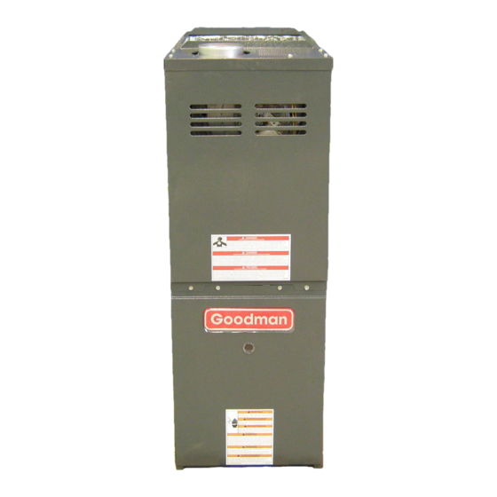
Goodman GMS8 Technical Manual
Gms8 series 33-3/8" 80% gas furnace units 80% afue, single stage, multi-speed, upflow horizontal
Hide thumbs
Also See for GMS8:
- Installation & operating instructions manual (32 pages) ,
- Technical manual (17 pages) ,
- Product specifications (12 pages)
Table of Contents
Advertisement
GMS8 33-3/8" 80% Gas Furnace Units
Multi-Speed, Upflow Horizontal
•
Refer to Service Manual RS6610004 for installation, operation, and troubleshooting information.
•
All safety information must be followed as provided in the Service Manual.
•
Refer to the appropriate Parts Catalog for part number information.
•
Model numbers listed on page 3.
This manual is to be used by qualified, professionally trained HVAC technicians
only. Goodman does not assume any responsibility for property damage or
personal injury due to improper service procedures performed by an unqualified
person.
Copyright ©2009 Goodman Manufacturing Company, L.P.
TECHNICAL MANU
TECHNICAL MANU
TECHNICAL MANU AL
TECHNICAL MANU
TECHNICAL MANU
80% AFUE, Single Stage,
AL
AL
AL
AL
®
C
US
RT66220010
May 2009
Advertisement
Table of Contents

Subscribe to Our Youtube Channel
Summary of Contents for Goodman GMS8
- Page 1 Model numbers listed on page 3. ® This manual is to be used by qualified, professionally trained HVAC technicians RT66220010 only. Goodman does not assume any responsibility for property damage or personal injury due to improper service procedures performed by an unqualified May 2009 person.
-
Page 2: Product Identification
Disconnect ALL power before servicing or installing this unit. Multiple power sources may be present. Failure to do so may cause property damage, personal injury or death. Goodman will not be responsible Installation and repair of this unit WARNING WARNING... - Page 3 WARNING that is not design certified by damage, personal injury, or death, Goodman for use with this unit. do not store combustible materials or use gasoline or Serious property damage, personal injury, reduced unit other flammable liquids or vapors in the vicinity of this performance and/or hazardous conditions may result appliance.
-
Page 4: Product Design
NFPA 54/ANSI Z223.1 - latest edition. In Canada, the fur- naces must be vented in accordance with the National Stan- The GMS8 furnaces are equipped with an electronic ignition dard of Canada, CAN/CSA B149.1 and CAN/CSA B149.2 - device used to light the burners and an induced draft blower latest editions and amendments. -
Page 5: Component Identification
COMPONENT IDENTIFICATION Tubular Heat Exchanger Pressure Switch Flue Pipe Connection Induced Draft Blower Gas Line Entrance Gas Valve Rollout Limit Junction Box Wiring Harness Grommet Gas Manifold Gas Line Entrance (Alternate) Inshot Burner Transformer Circulator Blower Blower Door Interlock Switch Note: Primary Limit Not Shown Integrated Control Module Upflow/Horizontal... - Page 6 PRODUCT DIMENSIONS GMS8 Alt. Gas Inlet Alt. Gas Inlet Alt. High Voltage High Voltage Inlet Low Voltage Alt. LowVoltage MODEL GMS80453A*C* 12-1/2 GMS80703A*C* GMS80704B*C* 17-1/2 GMS80904B*C* GMS80905C*C* 19-1/2 GMS81155C*C* 24-1/2 GMS81405D*C* All dimensions are in inches. GMS81405D* not available in Low NOx...
- Page 7 PRODUCT DESIGN GMS8 Pressure Switch Trip Points Trip Point ID Blower ID Blower Pressure Model Pressure Switch Switch Part # -0.70 B1370158 GMS80453A*C* GMS80703A*C* -0.70 B1370158 GMS80704B*C* -0.75 B1370179 GMS80904B*C* -0.75 B1370179 -0.75 B1370179 GMS80905B*C* GMS81155C*C* -0.90 0130F00041 GMS81405D*C* -0.80 0130F00042 For installations in Canada, the GMS furnaces are certifed only to 4,500 ft.
- Page 8 A large array of Amana ® brand coils are available for use with the GMS8 furnaces, in either upflow or horizontal applica- tions. These coils are available in both cased and uncased models (with the option of field installed TXV expansion device).
- Page 9 PRODUCT DESIGN Thermostats: ® The following Amana brand thermostats are suggested for use with GMS8 Furnace Models: THERMOSTATS Thermostat Man/Auto Programmable Cool Heat Batt. Powered Batt. Bkup 1213406* Man. Or Auto 1213407 Man. Changeover 1213411 Man. Changeover *1213406 is the recommended model for the G*S* furnaces when used with a heat pump in a fossil fuel application.
- Page 10 FURNACE SPECIFICATIONS GMS8 MODEL Btuh Input (US) High Fire 45,000 70,000 70,000 90,000 90,000 115,000 140,000 Output (US) High Fire 36,000 56,000 56,000 72,000 72,000 92,000 112,000 A.F.U.E. Rated External Static (" w.c.) .20 - .50 .20 - .50 .20 - .50 .20 - .50...
-
Page 11: Blower Performance Specifications
BLOWER PERFORMANCE SPECIFICATIONS GMS8 (CFM & Temperature Rise vs. External Static Pressure) EXTERNAL STATIC PRESSURE (Inches Water Column) Tons AC Model Motor at 0.5" Heating Speed Speed As Shipped CFM RISE CFM RISE CFM RISE CFM RISE CFM RISE CFM CFM CFM... - Page 12 BLOWER PERFORMANCE SPECIFICATIONS...
- Page 13 GMS8 WIRING DIAGRAMS Wiring is subject to change, always refer to the wiring diagram on the unit for the most up-to-date wiring.
- Page 14 IGNITOR VALVE PRESSURE SWITCH TYPICAL SCHEMATIC GMS8 * MODEL FURNACES WR 50T55-289 INTEGRATED IGNITION CONTROL This schematic is for reference only. Not all wiring is as shown above. Always refer to the appropriate wiring diagram for the unit being serviced.


Need help?
Do you have a question about the GMS8 and is the answer not in the manual?
Questions and answers