Mo-6900g series bottom-feed, overlock / safety stitch machine for extra heavy-weight materials and mo-6900j series variable top-feed, overlock / safety stitch machine for extra heavy-weight materials (4 pages)
Page 1
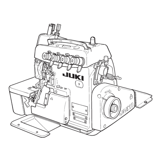
Super-High-Speed Overlock Machine High-Speed Overlock Machine / Safety Stitch Machine MO-6000S series MO-6900G series (for Extra-heavy-weight Materials) High-Speed Variable Top Feed Overlock Machine MO-6900R series MO-6900J series (for Extra-heavy-weight Materials) ENGINEER’S MANUAL 29355807 No.E350-01...
Page 2
PREFACE This Engineer’s Manual is written for the technical personnel who are responsible for the service and maintenance of the machine. The Instruction Manual for these machines intended for the maintenance personnel and operators at an apparel factory contains operating instructions in detail. And this manual describes “Standard Adjustment”, “Adjustment Procedures”, “Results of Improper Adjustment”, and other important information which are not covered by the Instruction Manual.
CONTENTS 1. SPECIFICATIONS ..................... 1 (1) MO-6700S SERIES ......................1 (2) MO-6900S SERIES ......................2 (3) MO-6900G SERIES ......................3 (4) MO-6900R SERIES ......................4 (5) MO-6900J SERIES......................5 2. MODEL NUMBERING SYSTEM ............... 6 3. STANDARD ADJUSTMENT ................8 (1) Adjusting the needle height....................
Page 4
(20) Adjusting the throat plate support ................34 (21) Adjusting the feed mechanism cover presser ............34 (22) Adjusting the looper cover ..................36 (23) Adjusting the cloth chip cover ................... 36 (24) Adjusting the needle mechanism................38 (25) Position of the upper looper lubrication pin ............. 40 1) Orientation of the lubricating pin ......................
Provided as standard Motor 2P 550W (In case of 7,000 rpm) 2P 400W (in case of less than 7,000 rpm) * JUKI MACHINE OIL 18 (Equivalent to ISO VG 18) Part No. : MML018900CA (900 mR R R R R )
2P 550W (In case of not less than 7,000 rpm) 2P 400W (In case of less than 7,000 rpm) * JUKI MACHINE OIL 18 (Equivalent to ISO VG 18) Part No. : MML018900CA (900 mR R R R R )
Needle thread heat remover Provided as standard (Excluding some of subclass machines) Micro presser lifting device Provided as standard Motor 2P 400W * JUKI MACHINE OIL 18 (Equivalent to ISO VG 18) Part No. : MML018900CA (900 mR R R R R )
2P 550W (In case of not less than 7,000 rpm) 2P 400W (In case of less than 7,000 rpm) * JUKI MACHINE OIL 18 (Equivalent to ISO VG 18) Part No. : MML018900CA (900 mR R R R R )
Provided as standard (Excluding some of subclass machines) Needle thread heat remover Provided as standard Micro presser lifting device 2P 400W Motor * JUKI MACHINE OIL 18 (Equivalent to ISO VG 18) Part No. : MML018900CA (900 mR R R R R )
2. MODEL NUMBERING SYSTEM MO-6000 SERIES MODEL NUMBERING SYSTEM 1 2 3 4 9 10 11 12 13 14 15 16 17 18 19 20 21 22 M O 6 – 5. 6 Seam code 4 Machine code 8 Needle gauge code Splicing 6700 series 1-needle...
Page 11
13 Special machine code Special classification of machine, structure and specification other than gauge set Standard Feed dog provided with a lip Upper looper high throw type For swim suits Upper looper extra high throw type For zipper For splicing 15 to 18 Device and attachment code G02/Q141 Presser foot/tape guide for attaching tape...
3. STANDARD ADJUSTMENT Standard Adjustment (1) Adjusting the needle height When the needle(s) is in the highest position, the needle height from the throat plate surface should be as shown below. (Unit : mm) 6 04 Model 1-needle/ 2-needle : right 2-needle : left MO- 6 04S(R) - –...
Page 13
Adjustment Procedures Results of Improper Adjustment 1) Take off the upper cover, loosen setscrew 2 of needle driving ™ Any other needle height than forked crank 1 and move needle driving forked crank 1 up or specified here will badly affect down to adjust the needle height.
Standard Adjustment (3) Installing position of the needle clamp Needle clamp connecting stud 1 should fit with the bottom end of needle bar 2 or spaced within 0 to 0.5 mm. 0 to 0.5 mm Butt the needle clamp with the bottom end of the needle bar.
Page 15
Adjustment Procedures Results of Improper Adjustment 1) Loosen setscrew 3 and adjust, by slightly turning needle clamp ™ If the clearance provided 4, the clearance provided between the right-hand side needle between the needle and the and the lower looper (for 2-needle overlock machine) and the looper is excessive, the needle clearance provided between the needle hole in the throat plate thread will be likely to skip at the...
Standard Adjustment (5) Adjusting the lower looper 1) Returning amount of the lower looper The distance between the blade point of the lower looper and the center of the needle should be as follows when the lower looper is at the extreme left of its stroke. (Unit : mm) Dimension J Model...
Page 17
Adjustment Procedures Results of Improper Adjustment 1) Returning amount of the lower looper ™ Excessive return of the lower 1 Loosen setscrew 2 of lower looper support arm 1 and adjust looper tends to cause stitch lower looper 4 to make adjustment of the returning amount. skipping when filament thread is used.
Standard Adjustment (6) Position of the upper looper guide Vertical position : (Unit : mm) To be in close contact with the frame guide surface. 7 5.5 Laternal position : To be pressed against the upper looper guide support gauge 1. Upper looper 13131909...
Page 19
Adjustment Procedures Results of Improper Adjustment 1) Fit upper looper guide support gauge 1 over gauge fixing pin ™ If the upper looper guide has 3 which has been driven in frame 2 and secure the gauge improperly positioned vertically, with an O ring.
Standard Adjustment (7) Positioning the upper looper holder The distance between the bottom surface of the frame and the upper end of the upper looper holder pin 2 should be as shown below when the upper looper holder 1 is at the highest point of its stroke. (Unit : mm) Model Dimension...
Page 21
Adjustment Procedures Results of Improper Adjustment 1) Loosen the setscrew of upper looper ball arm 3 and setscrew ™ Inaccurately positioned upper 5 of the upper looper holder. l o o p e r h o l d e r w i l l c a u s e 2) Adjust the clearances between upper looper bracket 4 and excessive projection of the upper looper holder 1 to approximately 0.2 mm respectively,...
Standard Adjustment (8) Positioning the upper looper 1) Height of the upper looper The distance between the throat plate surface and the blade point of the looper should be as follows when the upper looper is at the extreme left of its travel. (Unit : mm) Dimension Model...
Page 23
Adjustment Procedures Results of Improper Adjustment ™ If the upper looper has been 1) Height of the upper looper 1 Set a hexagon screwdriver onto setscrew 2 at the end of upper p o s i t i o n e d t o o h i g h , a n looper bracket 1 to adjust height D.
Standard Adjustment (9) Adjusting the double chain looper (Applicable only to MO-6 16S/6916R, G, J series) 1) Returning amount of the double chain looper The distance between the needle center and the blade point of the double chain looper should be 1.5 to 2 mm when the looper is at the extreme left of its travel.
Page 25
Adjustment Procedures Results of Improper Adjustment ™ Excessive return of the double 1) Returning amount of the double chain looper 1 Loosen setscrew 2 of double chain lopper driving arm 1 to chain looper will cause frequent make this adjustment. stitch skipping when filament 2 Radius M of the double chain looper driving arm 1 will be thread is used.
Standard Adjustment (10) Adjusting the height and clearance of the needle guard 1) For 1-needle or 2-needle overlock machine Make needle guard A lightly come in contact with the top end of needle (bend needle by 0 to 0.05 mm) when the blade point of the lower looper reaches the needle center. The clearance between needle guard B and the needle is 0.1 mm when the needle is at the lowest point of its stroke.
Page 27
Adjustment Procedures Results of Improper Adjustment ™ Excessively close contact between 1) For 1-needle or 2-needle overlock machine the needle guard A and the 1 Adjust needle guard A with setscrews 1 in the needle guard needles will lead to needle bend so that it lightly comes in contact with the needle (bend needle or stitch skipping.
Standard Adjustment (11) Adjusting the height of the feed dog The height of main feed dog 2 from the top surface of the throat plate 1 should be as follows when it is at its highest posion. (Unit : mm) Needle Model Dimension A...
Page 29
Adjustment Procedures Results of Improper Adjustment 1) Adjust the height of main feed dog 2 to dimension A with ™ If the feed dogs are too high, the setscrew 5. needles will be deflected and 2) Adjust the height of differential feed dog 3 with setscrew 7 so broken when sewing heavy- that there is no difference in level between main feed dog 2 weight materials.
Standard Adjustment (13) Adjusting the differential feed ratio MO-6000S, R Serise Pin at its highest Pin at its position Washer lowest Center position of nut Lower marker line (Max, stretching) (Max, gathering) (Standard) Gathering: 1: 2 Gathering: 1:1.6 Gathering: 1: 4 Stretching: 1: 0.7 Stretching: 1:0.6 Stretching: 1: 1.3...
Page 31
Adjustment Procedures Results of Improper Adjustment 1) Remove cover 1 on the rear of the frame and loosen main feed pin and nut 3. 2) Move main feed pin 2 up or down to adjust the differential feed ratio. 3) Adjust so that the lower engraved marker line on main feed rocker 4 aligns with the center of nut 3.
Standard Adjustment (15) Adjusting the presser foot 1) Adjusting the tilt of the presser foot The presser foot should be positioned so that the feed dogs go down under the specified presser foot pressure, and the presser foot sole comes in contact evenly with the throat plate surface. Throat plate 2) Adjusting the micro-lifting mechanism of the presser foot...
Page 33
Adjustment Procedures Results of Improper Adjustment 1) Adjusting the tilt of the presser foot ™ Uneven contact will result in bad 1 Turn the handwheel and place the feed dog in the position straight material feed, weak feed where the feed dog does not jut out the top surface of the throat power, or puckering.
Standard Adjustment (16) Positioning the upper knife arm shaft The upper knife shaft should be positioned 34 mm above the top surface of the throat plate when it is at its highest position. MO-6 16S(R)-F 6-60H : 35 mm 34 mm (17) Positioning the upper and lower knives, and available overedge widths 1) Lower knife Throat plate...
Page 35
Adjustment Procedures Results of Improper Adjustment 1) Remove the upper cover, loosen setscrew 2 in upper knife ™ Improperly positioned upper driving arm 1, and turn upper knife shaft 3 to adjust the position knife arm shaft will come in from the top surface of the throat plate to 34 mm.
Standard Adjustment (18) Resharpening of the knife Lower knife gauge Part No. 11996907 55˚ 10˚ (19) Position of the thread cam (Applicable only to MO-6 16 series) 1) Adjustment of the thread cam Level MO-6 16 series 2) Adjusting looper thread cam thread guides A and B and the looper thread cam nail Level...
Page 37
Adjustment Procedures Results of Improper Adjustment ™ If the 10˚ angle of the lower knife 1) When the knives have become dull, fully resharpen lower knife 1 until the contact mark of it disappears. is exceeded, the durability of the 2) When the upper knife has become dull, replace it with a new knife will be deteriorated, often one.
Standard Adjustment (20) Adjusting the throat plate support Uniform contact (21) Adjusting the feed mechanism cover presser (22) Adjusting the looper cover ™ The looper cover should smoothly close without coming in contact with upper knife 1 when slowly closing looper cover 2 with upper knife 1 in its lowest position of its troke. Cloth chip cover Frame...
Page 39
Adjustment Procedures Results of Improper Adjustment 1) Loosen setscrews 1 and adjust so that throat plate support 2 ™ If the throat plate support comes should not come in single-sided contact but come in uniform in single sided contact with the contact with throat plate 3 using setscrews 1.
Standard Adjustment (23) Adjusting the cloth chip cover ™ When cloth chip cover 3 is pressed away from you, it should not rattle. In addition, the cloth chip cover should not come in contact with upper knife 1 and lower looper 4. (Located inside)
Page 41
Adjustment Procedures Results of Improper Adjustment 1) Loosen setscrew 5 and temporarily tighten the setscrew with cloth chip cover stopper 6 raised. 2) Loosen setscrews 7 in the cloth chip cover, and adjust the longitudinal position of cloth chip cover 3. 3) Loosen setscrew 5 in the cloth chip cover stopper again, and press cloth chip cover stopper 6 downward until the stopper slightly comes in contact with looper cover 2.
Standard Adjustment (24) Adjusting the needle mechanism 1. Disassembling 2. Adjustment (It should not stay inside the pin as the concave.) Needle drive arm Chamfered portion should be positioned inside. 0.1 mm...
Page 43
Adjustment Procedures Results of Improper Adjustment 1. Disassembling 1) Remove top cover 7 and side cover 8. 2) If packing 9 of the top cover has been adhered on the frame, also remove packing 9. 3) Remove needle front plug !1 . 4) Loosen setscrew ! 0 of needle lubricating pin 4 and remove needle lubricating pin 4.
Standard Adjustment (25) Position of the upper looper lubricating pin 1) Orientation of the lubricating pin Oil inlet 2 of upper looper lubricating pin 1 should face upward. 2) Setting the lubricating pin The clearance provided between upper looper lubricating pin 1 and upper looper bracket 4 should be 0.15 mm.
Page 45
Adjustment Procedures Results of Improper Adjustment ™ If the oil inlet does not face 1) Orientation of the lubricating pin 1 When upper looper lubricating pin 1 is set with oil inlet 2 upward, oil will not be fed faced upward, lubricating hole 3 is in the lower section as resulting in seizure.
Standard Adjustment (26) Longitudinal momentum of the top feed dog (Top feed amount) Longitudinal momentum (top feed amount) of the top feed dog is possible up to 7.5 mm. Longitudinal momentum (top feed amount) Max. Min. Standard 7.5mm MO-6916R-F 6- 2.5mm MO-6900J 2.7mm...
Page 47
Adjustment Procedures Results of Improper Adjustment ™ If the min. stroke is decreased 1) Changing the longitudinal momentum (top feed amount) of the top feed dog to 1 mm or less, the components 1 Loosen top feed lock nut 3 and move top feed lever 4 in the mounted inside the machine direction of the arrow mark to adjust the stroke.
Standard Adjustment (27) Vertical momentum of the top feed dog Relation between the position of vertical adjustment pin and the vertical momentum Vertical momentum Application Adjusting position Striking to end of groove. 3.5mm Light weight material Marker line position A 5.0mm Light- to medium-weight materials Medium- to heavy-weight materials...
Page 49
Adjustment Procedures Results of Improper Adjustment 1) Remove the top cover, locus cut base 3 and exhaust slot ™ When the position of vertical support 4. adjustment pin 2 is changed, 2) Loosen vertical adjustment nut 1 and move vertical adjustment the vertical momentum of top pin 2 to a proper position.
Standard Adjustment (28) Adjusting the height of the top feed dog Adjusting the position of lowest point of the top feed dog It is standard that the top feed dog is 1.0 mm (safety stitch machine : 0.8 mm) from the top surface of the throat plate when the top feed dog is in the lowest point of its stroke.
Page 51
Adjustment Procedures Results of Improper Adjustment 1) Loosen setscrew 1 in the top feed dog and move top feed dog ™ When top feed dog is installed 2 up or down to adjust the height. higher than the standard (Caution) 1. Perform the adjustment in the state that the S e w i n g o f h e a v y - w e i g h t standard top feed pressure is applied.
Standard Adjustment (29) Locus cut of the top feed dog Locus cut mechanism makes longer the section where the feed dog actually feeds cloth by leveling the lower side of the locus of top feed dog motion. By this mechanism, the effect of prevention of irregular stitches can be obtained when sewing materials thicker than medium- weight ones such as knitted fabrics or the like although the effect is less for light-weight materials.
Page 53
Adjustment Procedures Results of Improper Adjustment ™ The lifted amount from the 1) Remove the top cover. 2) Turn the handwheel to bring the top feed dog to the lowest lowest point in the step 3) is the point of its stroke. cut amount.
Standard Adjustment (31) Adjusting the lateral position of the top feed dog Clearance between top feed dog 4 and presser 3 is 0.2 mm. a = a’ (0.2 mm) b = b’ (0.2 mm) a’ b’ Top feed arm C (Caution) 1.
Page 55
Adjustment Procedures Results of Improper Adjustment 1) Loosen the setscrew in the feed bar guide B. Refer to “(33) Adjusting the feed bar guides A and B”. 2) Remove the top cover and loosen setscrew 1 in the top feed arm C.
Standard Adjustment (32) Position of the motion of the top feed dog Adjusting the position of the motion of the top feed dog Loosen the setscrew in horizontal arm A 1 and move the position of horizontal arm A 1 to change the position of the motion of the top feed dog.
Page 57
Adjustment Procedures Results of Improper Adjustment ™Intermediate constant 1) Make horizontal arm A 1 in the state of temporary tightening, turn the handwheel and adjust the top feed dog to the position where it is desired to be constant. 2) At the position, tighten horizontal arm A 1 at the position where the top feed dog does not move even when the top feed lever is moved.
Standard Adjustment (32) Position of the motion of the top feed dog 1. The position of motion is adjusted to rear constant for 50H and 60H series and MO-6900J, and to intermediate constant for other models at the time of delivery so that the best locus suitable to the purpose of use can be obtained.
Page 59
Adjustment Procedures Results of Improper Adjustment ™Standard of the position where timing is advanced by 19˚from the upper dead point of the needle 1) Timing is advanced by approximately 21˚ from the upper dead point of the needle at the position where the hole in the periphery of the handwheen faces just under.
Standard Adjustment (34) Adjusting the top feed dog pressure <Standard height of top presser adjusting screw> Dimension A Vertical amount of Max. sewing speed top feed dog 24 to 25mm Less than 6.5mm 7,000rpm MO-6900R 20.5 to 21.5mm 6.5 to 8.5mm 7,000rpm 6,000rpm MO-6900J...
Page 61
Adjustment Procedures Results of Improper Adjustment Loosen top presser adjusting screw nut 1, when tightening top ™ When top feed dog pressure is presser adjusting screw 2, the top feed dog pressure is increased excessively low and feed force is increased. After the adjustment, be sure to tighten Top feed dog jumps and noise top presser adjusting screw nut 1.
Standard Adjustment (36) Height of the presser (pedal operation) Height of the presser from the top surface of the throat plate when the presser goes uo to the highest point (Unit : mm) Model Height of presser A (Max.) MO -6904R -0 4 -300 –1 0 6 -300 0 4 -500...
Page 63
Adjustment Procedures Results of Improper Adjustment 1) In the state that the presser pressure is applied, loosen presser ™ When the height of the presser turning lock nut 5 and adjust the height with presser lifter turning is excessively low, entering or setscrew 4 so that the height in the list is obtained when taking out of cloth becomes operating the presser lifting pedal.
Standard Adjustment (37) Lifting amount of the top feed dog (when the presser lifting lever is operated) It is the standard that the height from the top surface of the throat plate is 9 ± 0.5 mm when presser lifting lever 5 is pressed at the lowest point of the needle bar and top feed dog 7 goes up to the highest point.
Page 65
Adjustment Procedures Results of Improper Adjustment 1) Remove cloth base side cover 2 and top feed cover 1. ™ When the lifting amount of top feed dog 7 is excessively high, 2) Bring the needle bar to the lowest point of its stroke and keep top feed dog 7 at the height of 9 ±...
Standard Adjustment (38) Position of the thread guides and the looper thread take-ups MO-6 04S (R) MO-6 14S (R) MO-6 16S (R) Needle thread Needle thread take-up lever of guide 2-needle machine Needle thread take-up Needle thread take-up lever of Needle thread guide Needle Needle thread take-...
Page 67
Adjustment Procedures Results of Improper Adjustment ™ Distance a 1) Perform the adjustment by the setscrews. Position of the needle thread guide 1 and needle thread take up 2 lever is a very W h e n s e t s m a l l e r , b e t t e r important decisive factor when making soft chains since the tightness of needle thread needle thread take-up amount is increased in this case.
Standard Adjustment (39) Adjusting soft chain making mechanism 1) Replacing the parts with those exclusively designed for making soft chains 1 Needle thread presser plate C ..12112504 Cam face 2 Driving cam ........12112603 3 Needle thread presser spring B ..12112702 4 Throat plate ........
3) Important points in adjustment 1 Increase the thread take-up amount of the needle thread take-up lever. Refer to the adjustment values related to the needle thread guide and needle thread take-up lever. 2 Reduce the feed of the looper threads. (Mainly lower looper thread) Set J, K, L and M for the soft chain distances.
Standard Adjustment (40) Position of the thread guides and the looper thread take-ups of MO-6900G(J) MO-6904G (J) MO-6914G (J) MO-6916G (J) Needle thread take-up of Needle thread 2-needle machine guide 1.8mm Frame 15.8mm Frame Frame 16.5mm 15mm 26mm 33mm Needle thread take-up Needle thread Needle thread take-up of double-...
Page 71
MO-6904G (J), 6914G (J), 6916G (J) MO-6905G MO-6903G (Caution) The upper looper thread-take-up (right) and the looper thread take-up (left) shall be positioned at the extreme right point of the upper looper. (Unit : mm) Position MO-6904G(J)-0F6-700 MO-6914G(J)-CH6-700 MO-6916G(J)-F 6-700 MO-6905G-0M6-7 0 MO-6903G-0N6-3D1...
4. ADDITIONAL INFORMATION AND PRECAUTIONS (1) Thread tension 1) Strength of tension spring Part No. Color Natural length Operating Weight required to compress (mm) length (mm) spring to working length 8.92±0.49N (910 ± 50 g) 11550100 Purple 19.5 mm 11.5 mm 6.27±0.49N (640 ±...
37.5 MO- 6916G (J) - -700 (4) Caution in assembly 1) Application of sealant 1 Setscrew of the throat plate base (B) retainer 2 (JUKI seal) Frame Apply the sealant only to the right setscrew. Apply only to the right...
Page 74
4 Portion of the setscrews of the dust-proof rubber case (JUKI seal) Apply the sealant to the oil shield case setscrew 1 (1 pc.) and the dust-proof rubber case 2 setscrews (4 pcs.) 5 Oil shield plate assembly (JUKI seal) Apply the sealant to the inside of the oil shield plate 3.
1104 Three Bond 1212 JUKI exclusive part Nos. of the above 3 kinds of the sealants are not set. 2) Precautions to be taken with respect to the lubricating components Feed bar components ™ Be careful of the orientation of the oil shield rubber 4 and the dust-proof rubber 5.
(5) Kinds of motor pulleys, belts and frame support plate bolts 1) Motor pulleys and belts MO-6 00S(R) 60 Hz 50 Hz Sewing speed of Outside diameter Outside diameter sewing machine V-belt V-belt of motor pulley of motor pulley (rpm) Semi-sunken Fully-sunken Semi-sunken...
2) Pat No. of frame support plate bolt 1 Semi-sunken type Support plate bolt (A) 13155007 Locknut NS6240630SE Washer WP1002036SE Spring washer WS1002560KR 2 Fully-sunken type Support plate bolt (C) 13155106 Support plate bolt (D) 13155205 Locknut NS6240630SE Washer WP1002036SE Spring washer WS1002560KR Difference of support plate bolts (A), (C) and (D)
5. ADJUSTMENT OF THE NEEDLE HEIGHT AND LOOPER TIMMING (1) MO-6000 SERIES Needle height Upper looper components Lower looper components Double-chain looper Description 1- needle 2- needle 3-needle Marker of 1-needle 2-needle Upper looper Projection of Height of pin C e n t e r - t o - Feed amount Feed amount overlock...
6. TROUBLES AND CORRECTIVE MEASURES Trouble Case (1) Case(2) Check and Corrective measures Page 1. Needle thread breakage Threading The thread is entangled with the thread guide, or the Refer to the threading diagram. machine head has been incorrectly threaded. Thread path Scratches, burrs or rust on the pawls or needle holes of Remove such scratches, burrs, etc.
Page 81
Trouble Case (1) Case(2) Check and Corrective measures Page 2. Looper thread breakage Thread path Scratches, burrs, rust, etc, on the paw of the throat plate, Remove such scratches, burrs, etc. and carry out thread stitch tongue, looper, looper thread take-up, thread path finishing.
Page 82
Trouble Case (1) Case(2) Check and Corrective measures Page From the previous page Needle guards A needle guard has been improperly positioned, causing Refer to the pertinent Standard Adjustment. the needle point to strike it. Needle No. The needle is too thin for the materials. Replace the needle with a thicker one.
Page 83
Trouble Case (1) Case(2) Check and Corrective measures Page From the previous page Height of needle The needle has incorrect height and does not properly Refer to the related Standard Adjustment. 8, 12 pick up loops even if the looper has a correct return. Needle heat Stitch skipping occurs before the thread breaks due to Refer to the clause relating to the needle thread breakage...
Page 84
Trouble Case (1) Case(2) Check and Corrective measures Page 7. Upper looer thread stitches are skipped. Threading The thread has been entangled with a thread guide. See the threading diagram. Threading has not been done correctly. The needle does not take the upper looper Needle height The needle, if positioned too high or low, may fail to Refer to the related Standard Adjustment...
Page 85
Trouble Case (1) Case(2) Check and Corrective measures Page From the previous page Adjustment of looper Clearance or returning amount is not correct. Refer to the related Standard Adjustment. Thread tension The thread tension is too high, preventing formation of Reduce the tension.
Page 86
Trouble Case (1) Case(2) Check and Corrective measures Page 10. Triangle double chain needle thread stitches Double chain looper The chain looper is too high and too close to the throat Correct the height of the chain looper by pushing it down are skipped.
Page 87
Trouble Case (1) Case(2) Check and Corrective measures Page 12. Problems with double chain stitch chain-off Adjustment of loopers Adjustment of the loopers for producing chain-off thread Refer to the related Standard Adjustment. thread. without materials requires higher accuracy. Needle Guard The needle guard (C) is too high, damaging loops.
Page 88
Trouble Case (1) Case(2) Check and Corrective measures Page 13. Overlocking needle thread is loose. Position of the needle thread take-up guide and They are positioned too high, and the thread take-up Refer to the pertinent Standard Adjustment. needle thread guide draws out excessive needle thread.
Page 89
Trouble Case (1) Case(2) Check and Corrective measures Page 16. Uneven double chain stitches Thread tension The looper thread tension is not enough. Slightly increase the tension. Presser foot The presser foot comes into contact with the throat plate Make the presser foot come into contact with the throat unevenly.
Page 90
Trouble Case (1) Case(2) Check and Corrective measures Page 20. Uneven material feed Presser foot pressure The presser foot pressure is too high. Reduce the presser foot pressure except for the uneven material feed due to packering. Presser foot The hinge is too stiff. Remove the stiffness provided no hinge play is produced.
Trouble Case (1) Case(2) Check and Corrective measures Page From the previous page Presser foot pressure The presser foot pressure is not high enough, providing Increase the presser foot pressure. poor ironing effect. Differential feed ratio The differential feed ratio has been set for gathering. Set it for stretching.
(26) 125±1 37.5 Leg installing position Push button switch installing position (806) JUKI logotype Top of table Type : Helvetica Reg. Condensed This plane is finished Condensed voided letters (ø26) (ø26) in the method same as 37.5 the outside wood.
Page 93
Location of silk screening on the table surface Screw Lid support plate Section Y-Y Section X-X Section Z-Z ø26 (ø26) 30˚ JUKI logotype (silk screening) Brand label location indicating of drawing (Note) All dimensions are in millimeter. (ø10) (ø8.5) Part No. of table : 11959558...
Page 94
FAX : (81)3-3430-4909 • 4914 • 4984 The description covered in this engineer's manual is subject to change for improvement of the TELEX : J22967 commodity without notice. Copyright c 2002 JUKI CORPORATION. All rights reserved throughout the world. 02 · 10 Printed in Japan (E)
Need help?
Do you have a question about the MO-6000S series and is the answer not in the manual?
Questions and answers