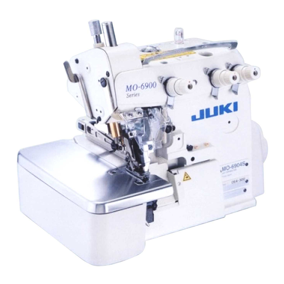
JUKI MO-6904S Instruction Manual
Hide thumbs
Also See for MO-6904S:
- Handbook (257 pages) ,
- Instruction manual (92 pages) ,
- Engineer's manual (96 pages)
Table of Contents
Advertisement
Advertisement
Table of Contents

Related Manuals for JUKI MO-6904S


Summary of Contents for JUKI MO-6904S
- Page 1 ASN-690 INSTRUCTION MANUAL...
-
Page 2: Table Of Contents
CONTENTS 1. CONFIGURATION OF THE MACHINE ............1 2. SPECIFICATIONS ..................2 3. INSTALLATION ................... 3 3-1. Removing packing materials ......................3 3-2. Securing the machine ........................3 3-3. Installing the dust collector ......................4 3-4. Installing the stacker ......................... 5 3-5. - Page 3 7. MAINTENANCE ..................37 7-1. Adjusting the knife ........................... 37 7-2. Cleaning the machine head ......................37 7-3. Checking the cartridge filter and replacing it ................38 7-4. Changing the machine oil ....................... 38 7-5. Changing needles ..........................39 7-6. Drainage of filter regulator ......................39 7-7.
-
Page 4: Configuration Of The Machine
1. CONFIGURATION OF THE MACHINE A Main body structural mechanism section K Side cutter L Dust collector (table stand, machine support and sewing table M Pneumatic controller covers) B Stacker unit N Power switch C Sub-table O Starting pedal for the sewing machine D Cloth plate P Thread trimmer presser E Sewing machine head Q Cloth feeding air blow... -
Page 5: Specifications
2. SPECIFICATIONS Machine head MO-6904S 1-needle overlock machine Max. 8,000 sti/min * Sewing speed Stitch system JIS E13 (USA standard : 504) Stitch length 0.8 to 4 mm Overedging width 4.0 mm (E), 4.8 mm (F), 5.6 mm (G) Needle ORGAN DC x 27 #9 to #14 (Standard : #11) -
Page 6: Installation
3. INSTALLATION 3-1. Removing packing materials Remove the string which secures the power cable. Remove the tape which secures the cloth plate. Remove the string which secures the hose. 3-2. Securing the machine CAUTION To avoid possible personal injuries, be sure to move the machine to a level and stable place and lock casters ❶ . ❶ – 3 –... -
Page 7: Installing The Dust Collector
3-3. Installing the dust collector CAUTION : ❹ If the dust collector is not securely in- stalled, blown-out dust or lint can get in eyes, resulting in personal injury. Plug the filings blowing hose ❷ and the chain- ❷ off thread blowing hose ❸ into the dust collec- ❺ tion box ❶ . Install filter ❹ so that it completely covers the top of the box. -
Page 8: Installing The Stacker
3-4. Installing the stacker CAUTION Be sure to carry out installation of the stacker by two or more workers in order to protect against accidents caused by the stacker unit when it accidentally falls. Install the stacker unit on the base with screws ❶ and washers ❷ (at two locations each). Adjust adjusting bolt ❸ to make the support rod of the stacker parallel to the installing plane. ❶ ❷ ❸... -
Page 9: Installing The Stacker Cloth Guide
3-5. Installing the stacker cloth guide Installing stacker cloth guide ❶ on the guide base with hand screw ❷ and washer ❸ . ❷ ❸ ❶ Adjust the orientation of the cloth guide according to the clamping position at the stacker unit ❹ . ❶ Material feeding direction ❹... -
Page 10: Installing The Cloth Plate And The Cloth Guide Unit
3-6. Installing the cloth plate and the cloth guide unit Place the cloth plate on the sewing machine table. Cloth plate Put the slots (at two locations) in the cloth guide unit as illustrated in the figure over two studs ❶ (at two locations) of the cloth plate over. Fix the studs ❶... -
Page 11: Installing The Thread Stand
3-7. Installing the thread stand Insert the thread stand into the hole in table ❶ with a washer placed between them and fix with the nut and washers from under the table as illustrated in the figure at left. Washer ❶ Washer Spring washer 3-8. Installing the regulator Fix regulator ❶... -
Page 12: Connecting The Air Coupler
3-9. Connecting the air coupler Connect the air coupler ❶ supplied with the unit as an accessory firstly to air hose ❷ , secondly to cou- pler ❸ on the main body side. ❸ ❶ ❷ Make sure that the pressure gauge of the regulator reads 0.5 MPa. 3-10. Connecting the starting pedal for the machine Connector ❷ of starting pedal ❶ to junction connec- tor ❹... -
Page 13: Joining The Sub-Table (Only For The Long Table Type)
3-11. Joining the sub-table (only for the long table type) CAUTION Connect the sub-table to the main-body table taking care not to allow your fingers caught between them. Main-body table ❹ ❶ ❷ Sub-table ❸ Butting the sub-table and the main-body table with no clearance provided between them, fix clips ❶ (at three locations) with thumbscrews ❷ . Lock casters ❸ (at four locations) to secure the sub-table. A difference in height between the top face of the main-body table and that of the sub-table may be observed on some installation site. - Page 14 CAUTION : To protect against possible personal injury or death, be sure to connect the tables while supporting the machine by four or more workers. If the difference in height between the sub-table and the main-body table cannot be eliminated with spacer ❹ , adjust the height of the main-body table (or the height of the sub-table). Main-body table Sub-table ❺ ❺ ❻...
-
Page 15: Connecting The Power Plug
3-12. Connecting the power plug CAUTION To prevent possible accidents caused by leakage or dielectric strength, an appropriate power plug shall be installed by a person who has an expert knowledge of electricity. Be sure to connect the power plug to the receptacle that is well grounded. Connection of the power plug to the power depends on the specifications of the product. Adjust the power plug to the power specifications to connect. ① In case of the product of single-phase, 200 to 240V specifications (CE specifications) : Connect the sky-blue and brown wires of the power cord to the power terminal (AC200 to 240V) and the yellow/green wire to the ground (earth) terminal respectively. -
Page 16: Installing The Cloth Receiving Board (Km-5) (Optional)
3-13. Installing the cloth receiving board (KM-5) (optional) ❶ ❷ ❹ ❸ ❺ ❺ Fix support rods ❷ on cloth holding table ❶ with wood screws ❸ and washers ❹ (at four locations each). Fix the cloth holding table mounted with the support rods on the sub-table with screws ❺ . The cloth holding table can be adjusted to four different heights using the fixing holes in the support rod. -
Page 17: Installing The 3-Pedal Unit (Pk-79) (Optional)
3-14. Installing the 3-pedal unit (PK-79) (optional) Connect the connector of the pedal to the junction connector coming from the control box. The figure shows differential feed switch ❶ , pause switch ❷ and high-/low-speed changeover switch ❸ from left to right. ❶... -
Page 18: Preparation
· Normally once every three to four days The chain-off thread trimmer has not been factory-oiled at the time of delivery. JUKI MACHINE OIL 18 should be used for lubrication. Remove oil cap ❶ . Pour JUKI MACHINE OIL 18 into the oil reser- ❶ voir. ❷ Supply oil until the pointer bar almost reaches ❷ the upper red marker line when oil gauge ❷ is observed from the side. -
Page 19: Threading The Machine
4-3. Threading the machine ★ How to remove the cloth plate Remove the cloth plate by holding the cloth plate guide base. Do not touch the curve sensor (optional) mounted on the cloth plate. To thread the machine head, remove the cloth plate in advance. When using an untwisted thread such as wooly nylon thread or weak thread, do not wind it round the intermediate thread guide. -
Page 20: Adjusting The Pressure Of The Presser Foot And Removing The Presser Foot
4-4. Adjusting the pressure of the presser foot and removing the presser foot Adjust the pressure of the presser foot by loos- ❶ ening first nut ❹ and turning presser foot adjust screw ❶ . ❹ When the adjust screw is turned clockwise, the ❸ pressure will increase. When it is turned coun- terclockwise, the pressure will decrease. -
Page 21: Differential Feed Mechanism
4-6. Differential feed mechanism CAUTION : To protect against possible personal injury due to abrupt start of the machine, be sure to start the following work after turning the power off and ascertaining that the motor is at rest. To carry out adjustment, remove the cloth plate in advance. Loosen differential feed lock nut ❷ . Move lever ❸ ❶ up for stretching stitch or down for gathering stitch. When you want to move the lever ❶ only slight- ly, use differential feed minute-adjust screw ❸... -
Page 22: Operation
5. OPERATION 5-1. Sewing procedure CAUTION : • Never start the machine with the eye protector cover raised in order to prevent injury accidents caused by the needle and the knife. • The machine becomes hot when it is running continuously or after it has run, never touch the sewing machine. Press ON button ❶ of the power switch to turn ON the power. When the buzzer is kept beeping imme- diately after turning ON the power, press OFF button ❷ on the sewing machine to turn OFF the power since connection of... - Page 23 Once the material has come out of the sensor, ❺ the machine stops after several stitches. The stacker operates when the stacker selector switch or stacker starting switch ❺ is depressed. CAUTION : • Do not place hands under the thread trimmer presser in order to protect against injury caused by trapping.
- Page 24 When sewing is completed, make sure that the sewing machine has stopped. Then, press the OFF button ❽ of the power switch to turn OFF the power. ❽ – 21 –...
-
Page 25: Explanation Of The Operation Panel
5-2. Explanation of the operation panel Ⓑ Ⓐ ❶ ❷ ❸ ❹ ❺ ❻ ❶ switch : Used for returning the setting to the initial value. ❷ switch : Used for changing the contents of setting. When this switch is pressed, changeable positions flash on and off. By pressing the switch, flashing position shifts in the left direction. Starting the machine is prohibited while the switch lamp is flashing on and off (setting mode). ❸... -
Page 26: Description Of The Pedals And The Switches On The Machine Head
5-3. Description of the pedals and the switches on the machine head Switch location Name and description of function ❶ Sewing machine starting pedal The machine starts at the chain-off thread setting speed (at the high speed if the manual start mode is selected) as long as this switch is held depressed. • When the automatic start mode is selected : When the material is detected, the automatic starting is given priority. -
Page 27: List Of Functions To Be Set
5-4. List of functions to be set Item Contents indication Description Setting range Operation indication (initial value) level 1 The number of seams, current seam 1 to 9 0 No. of pcs. counter 0 to 9999 0 Use/disuse of the stacker 0 to 1 0 Number of delay stitches for the thread trimming 0 to 99 stitches presser 0 Number of delay stitches for the stacker presser... -
Page 28: Details Of Selected Functions
5-5. Details of selected functions ① Setting of the number of seams (level 1) The number of seams for activating the stacker is set. The preset number of seams and the current seam are indicated. Current seam (the ordinal position of the seam being sewn with respect to the set number of stitches is indicated) Set value (setting range 1 - 9) ② Setting of the No. of pcs. counter (level 1) The number of pieces of products to be sewn is set. The No. - Page 29 ⑧ Setting the time for the stacker blow (level 1) The length of time during which the stacker blow works after the delay time for the stacker blow has elapsed. Setting range 0 to 9900 ms ⑨ Setting the delay time for lifting the thread trimmer (level 2) The time to elapsed before lifting the thread trimmer presser after the stacker blow has worked is set. Setting range 0 to 200 ms ⑩ Setting the speed of stitch for the high-speed mode (level 1) The speed of stitch for the high-speed mode is set.
- Page 30 ⑯ Setting of the start mode (level 2) The start mode of the machine is set. Either the automatic mode by the start sensor or the manual mode by the starting pedal is selected. 0 : Manual mode (The start sensor is inoperative.) 1 : Automatic mode (The starting pedal is used as the chain-off thread switch.) ⑰ Curve mode setting (level 1) Whether the curve sensor is used or not is selected.
-
Page 31: Other Settings
5-6. Other settings (1) Setting of the auto lifter function (optional) CAUTION : Ⓐ Ⓑ When the auto-lifter function is used, do not place your fingers under the presser foot. When the optional auto-lifter device (AK) is attached, the auto-lifter function is brought into action. Turn ON the power switch while pressing switch ❶ on the operation panel. LED display is turned to Ⓐ , Ⓑ (FL ON) with ❶... -
Page 32: Adjustment
6. ADJUSTMENT 6-1. Stacker support board adjustment CAUTION : To avoid possible accidents because of abrupt start of the machine or the device, turn OFF the power to the machine, and expel air remaining in the machine by removing the pipe of the air supply before carrying out assembling or adjustment works. (1) Adjusting the stacker height Adjust the support board ❶ in accordance with ❸ the type of material to be used. ❶ When handle ❷ is loosened, the support board ❺ can be moved up and down. When it is in the ❹... -
Page 33: Adjusting The Position Of The Thread Trimmer Presser
6-2. Adjusting the position of the thread trimmer presser Loosen screws ❷ (at two locations) which fix cylin- der mounting arm ❶ to adjust the arm to the right or left. Adjust the thread trimmer presser to the position at which it clamps the material to be sewn at the center of its width. -
Page 34: Adjusting The Edge Guide
6-4. Adjusting the edge guide CAUTION : Turn OFF the power before starting the work so as to prevent accidents caused by abrupt start of the sewing machine. Edge guide ❶ works to adjust the overedging ❹ width of the material. Adjust the overedging ❷ width by adjusting edge guide ❶ to the right or left using screws ❷ . Curl guide ❸ works to prevent the material edge from curling. -
Page 35: Adjusting The Cloth Guide
6-5. Adjusting the cloth guide CAUTION : Turn OFF the power before starting the work so as to prevent accidents caused by abrupt start of the sewing machine. By loosening two screws ❷ , cloth guide posi- ❶ tion can be adjusted in the direction shown by ❷ arrow. After the adjustment of overedging width of the material with edge guide ❹ , adjust the surface of edge guide ❹... -
Page 36: Adjusting The Cloth Chip Suction Force
6-7. Adjusting the cloth chip suction force CAUTION : Turn OFF the power before starting the work so as to prevent accidents caused by abrupt start of the sewing machine. Tightening adjustment screw ❶ weakens the chain- off thread suction power; loosening the screw strengthens it. ❶ The suction force for the cloth chip collec- tor and the dust collector mounted on the upper looper bracket is adjusted by means of the same adjusting screw. –... -
Page 37: Adjusting The Sensors
6-8. Adjusting the sensors Once the cloth guide has been adjusted to 5 mm position, check to be sure that the numeric value on the main digital display shown on the amplifier is 3500 or more when no material is placed under the sensor unit, and that the numeric value on the main digital display is 2500 or less when the material is placed under the sensor unit. - Page 38 (1) Setting the sensitivity of the amplifier for the start sensor and curve sensor Adjust the clearance provided between the cloth guide and cloth plate to 5 mm before starting adjustment. (Setting at the time of delivery) Turn on the power to the machine. Threshold (setting at the Amount of light time of delivery) Be sure to carry out adjustment under the received machine setting mode in order to prevent accidents caused by abrupt start of the...
- Page 39 (2) Setting thresholds for the start sensor and curve sensor The with-work position and the without-work position can be respectively detected to set the thresh- old for the amount of light received, to the middle point between the two position. Adjust the clearance provided between the cloth guide and cloth plate to 5 mm before starting adjustment. Turn on the power to the machine. Be sure to carry out adjustment under the Amount of light received Threshold machine setting mode in order to prevent accidents caused by abrupt start of the machine.
-
Page 40: Maintenance
7. MAINTENANCE 7-1. Adjusting the knife CAUTION : • To protect against possible personal injury due to abrupt start of the machine, be sure to start the following work after turning the power off and ascertaining that the motor is at rest. • To protect against possible personal injury, never touch the blade of the knife with fingers and hands. • To prevent possible accidents caused by inexperienced persons and those resulting from maladjustment, adjustment work should only be carried out by maintenance personnel who have received safety training and are familiar with the sewing machine. To adjust the extent of cutting fluff at the overedged edge of the material : Loosen setscrew ❶ . Tighten the setscrew with lower knife ❷ pressed to the left. Loosen setscrew ❸... -
Page 41: Checking The Cartridge Filter And Replacing It
7-4. Changing the machine oil CAUTION : Turn OFF the power before starting the work so as to prevent accidents caused by abrupt start of the sewing machine. Use JUKI MACHINE OIL 18 in the machine head. To change the oil, first drain the oil out by un- ❶ screwing screw ❶ on the tip of the oil drain hose connected to the oil pan. -
Page 42: Changing Needles
7-5. Changing needles CAUTION : To protect against possible personal injury due to abrupt start of the machine, be sure to start the following work after turning the power off and ascertaining that the motor is at rest. The standard needle is DC×27 #11. You can also use the DC×1 needle. In this case, however, the clearance provided between the needle and the ❶ looper may be required to be adjusted. If sewing need to be carried out with a finely adjusted thread tension, use the DC×27 needle. -
Page 43: Cautions For The Compressed Air Supply (Source Of Supply Air) Facility
In the aforementioned cases, be sure to install an air dryer. When the supply air contains a considerable amount of carbon and dust Mist separator (Most troubles in the air solenoid valves are caused by carbon.) Be sure to install a mist separator. Standard equipment supplied by JUKI Filter regulator Air solenoid valve Air cylinder Cautions for main piping • Be sure to slope main piping by a falling gradient of 1 cm per 1 m in the direction of air flow. -
Page 44: Dust Collector Box
7-8. Dust collector box CAUTION : Turn OFF the power before starting the work so as to prevent accidents caused by abrupt start of the sewing machine. Throw away waste cloth chips inside the dust collector box at least once a day. At this time, also clean up the filter. Fine cloth chip adhere to the suction port inside the box; blow them away with an air gun. If a great deal of lint adheres to the intake, the suction power may be reduced. -
Page 45: Consumable Parts To Be Replaced
7-10. Consumable parts to be replaced CAUTION : • Turn OFF the power before starting the work so as to prevent accidents caused by abrupt start of the sewing machine. • To protect against possible personal injury, never touch the blade of the knife with fingers and hands. • To prevent possible accidents caused by inexperienced persons and those resulting from maladjustment, adjustment work should only be carried out by maintenance personnel who have received safety training and are familiar with the sewing machine. The following parts are consumables. Be sure to periodically replace them with new ones. • Side cutter block Side cutter block (Part number : MAT02503000) If the block is not periodically replaced with a new one, it can wear out to fail to trim chain- off thread sharply, affecting the quality of thread trimming at the end of sewing. -
Page 46: Replacing The Fuse
7-11. Replacing the fuse CAUTION : To prevent personal injuries caused by electric shock hazards or abrupt start of the sewing machine, remove the cover after turning OFF the power switch and a lapse of 5 minutes or more. To prevent personal injuries, when a fuse has blown out, be sure to replace it with a new one with the same capacity after turning OFF the power switch and removing the cause of the blown-out of the fuse. -
Page 47: Adjusting The Belt Tension
[ Replacing fuse on PWR-T circuit board ] (Caution) The illustration below shows the PWR-T PCB. The type of PCB differs by destination. ❺ ❻ Holding the glass section of fuse ❺ , remove the fuse. (Caution) There is a risk of electrical shock when removing the fuse. Be sure to remove the fuse after LED ❻ has totally gone out. Be sure to use a fuse with the designated capacity. ❺ : 3.15 A/250 V Time-lag fuse (Power circuit protective fuse) Part number: KF000000080 Install the control box to the motor. -
Page 48: Destination Of Connection For Input/Output Connectors
7-13. Destination of connection for input/output connectors CAUTION : • To prevent personal injury caused by abrupt start of the sewing machine, carry out the work after turning OFF the power switch and a lapse of 5 minutes or more. • To prevent damage of device caused by maloperation and wrong specifications, be sure to connect all the corresponding connectors to the specified places. • To prevent personal injury caused by maloperation, be sure to lock the connector with lock. • As for the details of handling respective devices, read carefully the Instruction Manuals supplied with the devices before handling the devices. Solenoid valves and sensors used with ASN-690 are connected to the connectors inside the control box as described below: Connection state of the connectors can be checked by loosening front-cover fixation screws and opening the front cover. -
Page 49: Error Codes
7-14. Error codes In case of the following, check again before you judge the case as trouble. Phenomenon Cause Corrective measure When tilting the sewing machine, the When tilting the sewing machine Tilt the sewing machine after turning buzzer beeps and the sewing ma- without turning OFF the power switch, OFF the power. -
Page 50: Error Code List
7-15. Error code list Description of error detected Cause of occurrence expected Items to be checked E000 Execution of data initialization • When the machine head is changed. (This is not the error.) • When the initialization operation is execut- E003 Disconnection of synchro- • When position detection signal is not input •...
Need help?
Do you have a question about the MO-6904S and is the answer not in the manual?
Questions and answers