Table of Contents

Related Manuals for BNC 577


Summary of Contents for BNC 577
- Page 1 Operating Manual Version 0.10 Model 577 Pulse Generator Berkeley Nucleonics Corporation 2955 Kerner Blvd. San Rafael, CA 94901 Phone: 415-453-9955 Fax: 415-453-9956 Email: info@berkeleynucleonics.com Web: www.berkeleynucleonics.com...
- Page 2 WARRANTY In addition to a 30-day money back guarantee, the 577 has a two-year limited warranty from the date of delivery. This warranty covers defects in materials and workmanship. If repairs are required during the warranty period, contact the factory for component replacement or shipping instructions.
-
Page 3: Table Of Contents
......................5 IGITAL UTPUT ULTIPLEXER & I ................... 5 EPENDENT NDEPENDENT IMING VENTS MODEL 577 FRONT PANEL OVERVIEW ....................6 ......................6 ISPLAY AYOUT AND NDICATORS 4.1.1 LCD Screen ..........................6 4.1.2 Keypad (Pushbuttons) ......................7 4.1.3 Rotary Adjustment Knob ......................7 4.1.4... - Page 4 ......................... 20 THERNET NTERFACE 8.4.1 IP Address and Raw TCP/IP Connection ................20 8.4.2 Determining IP Address ......................20 8.4.3 Setting the 577 to Raw TCP Protocol ..................21 ..................22 ROGRAMMING OMMAND YPES AND ORMAT 8.5.1 Line Termination ........................22 8.5.2...
-
Page 5: Pulse Generator
1.2 Warranty In addition to a 30-day money back guarantee, the model 577 has a two-year limited warranty from the date of delivery. This warranty covers defects in materials and workmanship. If repairs are required during the warranty period, contact the factory for component replacement or shipping instructions. Include the serial number of the instrument. -
Page 6: Unpacking Caution
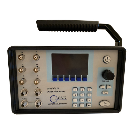
The Model 577 has been shipped with a Tilt Arm that is designed to be used as an adjustable tilt selector only. The Arm is not to be used as a handle for moving or carrying the unit. If the 577 it to be moved please pick it up by supporting the entire unit with your hands. -
Page 7: Safety Issues
2 Safety Issues The 577 has built in equipment protections to prevent harm to the unit and the user, if the equipment is used in a manner not specified by the manufacturer the protection provided by the equipment may be impaired. -
Page 8: Pulse Concepts And Operations
‘m’ times. The cycle is then repeated. Different modes may be selected for each output, allowing a wide variety of output combinations. Each output may also be independently disabled or gated (using the external gate input). Model 577 Operating Manual... -
Page 9: Digital Output Multiplexer
3.5 Dependent & Independent Timing Events The 577 allows the user to control the relationship between the Channel Timers by setting the sync source for each timer. Independent events are all timed relative to the internal T start pulse. -
Page 10: Model 577 Front Panel Overview
4 Model 577 Front Panel Overview 4.1 Display Layout and Indicators The Model 577 front panel has a keyboard, rotary adjustment knob, and a LCD display that allows the user to program all settings. 4.1.1 LCD Screen A 3”, 240x400 pixel TFT module displays all parameters and status information. The status information is located in the upper portion of the display. -
Page 11: Keypad (Pushbuttons)
Next key and select the next parameter in the currently displayed menu. 4.1.4 BNC Connectors One Gate Input (GATE), one Trigger Input (TRIG), and up to 8 Channel Outputs are available on the front of the unit. Model 577 Operating Manual... -
Page 12: Model 577 Rear Panel Overview
The Model 577 can be operated from 100 to 240 V at a line frequency of 50-60 Hz. 5.1.2 Power Switch If this switch is used to turn the Model 577 off, changes that have been made to data or parameters will not be saved. 5.1.3 BNC Connectors External Clock input (CLK IN), and External Clock output (CLK OUT), are standard. -
Page 13: Navigating The 577 Front Panel
Navigating the 577 Front Panel 6.1 Selecting Menus Parameters are grouped in menus, selectable using the Blue Soft Keys, the Next key, and a Rotary Adjustment Knob. For example, to select the output channel parameters, press the Blue Soft Key corresponding to the Channel menu. -
Page 14: 577 Menu Structure
Selecting the Desired Menu The 577 has a built-in set of menus that can be accessed by pressing the right-most soft key. This sub-menu will allow the user to return to the System menu, select the Channel and Output menus, enable and configure a Gate or Trigger signal, Save or Recall previous settings, and change the Communications and Configuration settings. -
Page 15: Setting System Mode Of Operation
(Burst, On, Off, etc.) only when they are appropriate. Mode: Selects the T System Timer mode: Continuous, Single Shot, Burst or Duty Cycle. Continuous: Once started, T pulses are generated continuously. Select the rate of the pulses to be generated Model 577 Operating Manual... - Page 16 Single Shot: One T pulse is generated for each start command. Burst: Sets the number of pulses to be generated when in Burst mode. Model 577 Operating Manual...
-
Page 17: Setting The Internal Reference Source And Rate
In other words if you have a 35 MHz signal you must tell the 577 to look for a 40 MHz or higher, any choice below that will result in unpredictable results. -
Page 18: Setting The Output Reference
7.2.4 Setting the Output Reference The 577 also has the ability to output a clock signal to an external unit if so desired. The user can choose from any of the preset frequencies as well as outputting the T signal. If the unit is in external input mode and a different frequency is input than what the 577 is told to expect, the output would be a factor of the expected frequency. -
Page 19: Channel Menus
If a channel is displayed in white, it is enabled. If a channel is displayed in gray, the channel is disabled. 7.3.2 Channel Menu in Burst Mode The Burst Mode Channel Menu page includes an additional parameter to set the number of pulses in the burst. Model 577 Operating Manual... -
Page 20: Channel Menu In Duty Cycle Mode
The entered delay value is relative to the selected sync source. This source can be changed by pressing the Sync soft key while in the Channel Menu page. It is important to note that the 577 will not allow a circular chain of sync sources that would result in a channel triggering itself. -
Page 21: Output Menu
Ampl: Sets the output voltage level when in the Adjustable mode. For safety reasons the 577 should not be driven at 20 volts or higher into a 50 Ω load in either active low mode or in active high mode with a high Duty Cycle (90% or higher) for more than 1 min on any channel. -
Page 22: Saving And Loading Configurations
For example if all channels were set to 100µs pulse widths and one channel had a 50 µs delay, even if that channel was disabled, the 577 could not be retriggered faster than 150 µs. To ensure this does not cause triggering problems set unused channels to have a combined delay and width time less than the desired trigger rate. -
Page 23: Communication Configurations
Beeper Volume, and Key Repeat Rate can be changed to enhance the user interface. The system can also be set up to generate pulses automatically when powered on by enabling the Auto Start function. The DPM soft key will allow the user to choose English or European delimiter notation. Model 577 Operating Manual... -
Page 24: Information Menus
The menu will display the serial number of the unit, the model and code versions. The third information page will show what type of input/output module is installed in each bay of the device. The page will also show if the Dual Trigger or Communications upgrade option has been purchased. Model 577 Operating Manual... -
Page 25: Remote Communication
“*” character as the unit is booting up. This may result in an undesired lockup of the instrument. 8.1 RS-232 Interface The serial port is located on the back of the 577 and uses a 9-pin D-type connector with the following pin-out (as viewed from the back of the unit):... -
Page 26: Gpib Interface
GPIB address menu item. 8.4 Ethernet Interface A RJ- 45 jack is optional on the 577. This interface will use a module to transfer data through the Ethernet port to the host computer. 8.4.1... -
Page 27: Setting The 577 To Raw Tcp Protocol
Windows Firewall off while performing these tasks. When the utility sees the Digi device, it will display the currently assigned IP address in the list. 8.4.3 Setting the 577 to Raw TCP Protocol Note* Only follow this process if Raw TCP communications are desired, direct communications with a terminal program is the factory default method. -
Page 28: Programming Command Types And Format
8.5 Programming Command Types and Format The 577 Pulse Generator uses two types of programming commands: IEEE 488.2 Common Commands and Standard Commands for Programmable Instruments (SCPI). The format is the same for all interfaces. HyperTerminal (in Windows) or any other generic terminal program may be used to interactively test the commands using the RS232 interface. -
Page 29: Scpi Keyword Separator
Represents a single binary condition that is either true or false. True is represented by a 1 or ON; false is rep-resented by a 0 or OFF. Queries return 1 or 0. <identifier> Selects from a finite number of predefined strings Model 577 Operating Manual... -
Page 30: Error Codes
8.5.8 Error Codes The 577 responds to all commands with either: ok<cr><lf> or ?n<cr><lf> Where "n" is one of the following error codes: Incorrect prefix, i.e. no colon or * to start command. Missing command keyword. Invalid command keyword. Missing parameter. - Page 31 8.6 577 Commands (SCPI Command Summary) Keyword Parameter Range Notes :INSTrument The units' upper level command keyword :CATalog Returns a comma-separated list of the names of all the channels. Example: a two channel unit would return T , CHA, :FULL Returns a comma-separated list of the names of all the channels and their associated number.
- Page 32 *Note: To change this parameter the unit must be power cycled before the command will take effect. :SERNumber Query only. Returns the Serial Number the 577 :VERSion Query only. Returns the current Firmware and Bootloader versions installed on the 577 Main...
-
Page 33: Menu
Choose the edge to trigger on (only used when the option for the gate to be a second trigger input is enabled) :LEVel .20 V - 15 V Choose the gate level threshold to trigger on, this should be set to ~ 50% of the input potential Model 577 Operating Manual... - Page 34 *ARM Resets all channel counters simultaneously when the channels are in either single shot or burst mode. *Note: The system must be in continuous mode (this command is functionally the same as pressing the Run/Stop button). Model 577 Operating Manual...
- Page 35 *Note: For the gate to be used as a trigger source the unit must have the dual trigger option. :CGATe DIS / LOW / HIGH Sets the channel gate mode to Disabled, Active High or Active Low mode. Model 577 Operating Manual...
-
Page 36: Option Dt15 (Dual Trigger)
* The GATE Input functions as a standard Gate when not in “Dual Trig” or “ReArm” modes. Considering the event itself, or the documentation requirements that follow, enlist our team of spectroscopists with an Enhanced Reachback Program. Model 577 Operating Manual... -
Page 37: Option At35 (35V Output / Fast Rise)
While the 35 volt output provides a fast, controlled rising edge, the pulse width and falling edge are not tightly controlled. Also, when using the 35 V mode, the option will only function if the Polarity is set for Active High. Model 577 Operating Manual... -
Page 38: Option Tz50 (Ttl Impedance Matching)
4 Volts while in the TTL/CMOS Mode. All other functionality of the module is the same as the AT20 modules, including output while using the Adjustable Mode function of the channels. *Note: The TZ50 module has significant overshoot and ringing through high impedance (see figure below). Model 577 Operating Manual... -
Page 39: Option At45 (45V Output)
When an AT45 module is present, the system performs self-checks to insure the module is not damaged when attempting to over-drive, however the overdrive protection is NOT SHORT CIRCUIT PROTECTED, and caution must be taken to prevent damage to the board when driving into a short! Model 577 Operating Manual... -
Page 40: Module Errors
It takes approximately 30 sec to change from 45 V to 4.0 V so caution must be taken when adjusting the voltage to a lower voltage tolerant circuit. Model 577 Operating Manual... -
Page 41: At45 Scpi Command Extension Summary
4 V to 45 V Sets adjustable output level. :MERRor Command clears the last module error to allow the unit to generate pulses again. Query returns the last displayed error. High Z Load at 5 V Model 577 Operating Manual... - Page 42 High Z Load at 45 V Low Z Load at 5 V Model 577 Operating Manual...
- Page 43 Low Z Load at 45 V Rise time and overshoot are tuned for best response at low impedance (low Z) Rise Time vs. Output Voltage Model 577 Operating Manual...
- Page 44 Fall Time vs. Output Voltage Overshoot vs. Output Voltage Model 577 Operating Manual...
-
Page 45: Safety Marking Symbols
Class II Equipment protected by double insulation or IEC 417, No. 5172 reinforced insulation. The equipment typically does not require a Safety Ground (Protective Ground). ISO 3864, No. B.3.6 Caution, risk of electric shock IEC 417, No. 5041 Caution, hot surface Model 577 Operating Manual... - Page 46 Indicates compliance with the WEEE Directive. Please dispose of the product in accordance with local regulations and conventions. Indicates compliance with European Union Legislation for the relevant Safety (Low Voltage CE Mark Directive 2006/95/EC) and EMC (EMC Directive 2004/108/EC) requirements. Model 577 Operating Manual...
-
Page 47: Model 577 Specifications
14 Model 577 Specifications I/O Configuration 577 – 2C: 2 Independent Channels Model/Output 577 – 4C: 4 Independent Channels 577 – 8C: 8 Independent Chann els Output Modules: Standard AT20 Dual Channel, TTL/CMOS & Adjustable Output Module Optional Dual Channel, 820 nm Optical Output Module... - Page 48 2.8 ns typ (10% - 90%) Slew Rate > 0.5 V/ns Jitter 50 ps RMS channel to channel Adjustable Mode: Output Impedance 75 Ohms Output Level 2.0 to 20 VDC into 1 Kohm 0.8 to 8.0 VDC into 50 ohm Model 577 Operating Manual...
- Page 49 <1.4 ns RMS AT35 Specifications Through a 50Ω load at 200 Hz 5 V – 35 V Output Setpoint Resolution 10 mV Rise Time < 30 ns Accuracy 500 mV Max. Frequency (Internal & External) 4000 Hz Model 577 Operating Manual...
- Page 50 Pulse Width - High Z (>10k) 10 ns to DC Pulse Width - Low Z (50 Ohms) 10 ns to 10s Current (maximum) 35 mA (High Z @10ms width) 900 mA (Low Z @ 10ms width) Model 577 Operating Manual...
Need help?
Do you have a question about the 577 and is the answer not in the manual?
Questions and answers