Table of Contents

Subscribe to Our Youtube Channel
Related Manuals for Euro-Kitchen AirPRO 238 Professional Series


Summary of Contents for Euro-Kitchen AirPRO 238 Professional Series
- Page 1 Installation Guide and Users Manual AirPRO 238 Professional Series (PS29/PS31) IMPORTANT: Read and save these instructions. NOTICE: Installer: Leave this guide with the homeowner Homeowner: Keep this guide for future reference Wall Mount Range Hood...
-
Page 3: Important Safety Notice
Important Safety Notice Read all Instructions before Installing and operating this appliance • The installation in this manual is intended for qualified installers, service technicians or persons with similar qualified background. Installation and electrical wiring must be done by qualified profession- als and in accordance with all applicable codes and standards, including fire-rated construction. - Page 4 Euro-Kitchen, Inc. further declines all responsibility for injury due to negligence and the warranty of the unit automatically expires due to improper maintenance. Euro-Kitchen, Inc. will not be held responsible for any damages to personal property or real estate or any bodily injuries whether caused directly or indirectly by the range hood.
-
Page 5: Table Of Contents
Table of Contents INSTALLATION USE AND CARE Tools needed............3 Troubleshooting...........14 Parts supplied...........4 Use and care information.......15 Venting requirements........5 Specifications..........15 Mount heights & clearance......5-6 Measurements & Diagrams......16-21 Calculating vent system length.......6 MAINTENANCE Venting methods..........7 Cleaning..........22 Electrical requirements........8 Replacing the filter & light bulb.....22 Preparation............9 WARRANTY Installation..........10-11... -
Page 6: Parts Supplied
Parts supplied: plied: Upper Chimney Lower Chimney Range Hood Chimney-mounting Bracket Hood-mounting Bracket Qty: 4 PCS Qty: 2 PCS (30-in models) Qty: 3 PCS (36-in models) Qty: 6 PCS Qty: 4 PCS (30-in models) Qty: 6 PCS (36-in models) Qty: 2 PCS (30-in models) Qty: 3 PCS (36-in models) Qty: 4 PCS Qty: 4 PCS... -
Page 7: Venting Requirements
Venting Requirements Height & Clearance Chimney- • Vent system must terminate to the outside (roof or side wall). mounting Maximum ceiling clearance 110” at 30” hood mounting • DO NOT terminate the vent system in an at- Bracket height above countertop/ tic or other enclosed area. -
Page 8: Calculating Vent System Length
IMPORTANT: • A minimum of 6” round (standard for this range hood) or 3-1/4 x 10” rectangular duct (purchased separate- ly) must be used to maintain maximum airflow efficiency. • Always use rigid type metal/aluminum ducts if available to maximize airflow when connecting to provided duct. -
Page 9: Venting Methods
Venting Methods • This range hood is factory set for venting through the roof or wall. • Vent work can terminate either through the roof or wall. To vent through a wall, a 90° elbow is needed. IMPORTANT: • NEVER exhaust air or terminate duct work into spaces between walls, crawl spaces, ceiling, attics or garages. -
Page 10: Electrical Requirements
Electrical Requirements IMPORTANT: Observe all governing codes and ordinances. It is the customer’s responsibility: • To contact a qualified electrical installer. • To assure that the electrical installation is adequate and in conformance with National Electrical Code, ANSI/ NFPA 70 — latest edition*, or CSA Standards C22. 1-94, Canadian Electrical Code, Part 1 and C22. 2 No. 0-M91 - latest edition** and all local codes and ordinances. -
Page 11: Preparation
Preparation WARNING Excessive Weight Require three or more person to move and install this range hood. Spinal or other bodi- ly injuries could occur if it is not followed. Advanced Preparations: • Be familiar with the controls of the range hood by reading through Range Hood Operations, Page 12. -
Page 12: Installation
Installation Installations (refer to Page 4 for parts): Measure the distance between stove top and the bottom of range hood. A distance of 27” to 30” is recommended*. *Due to different ceiling height configurations, recommend- ed height may not be applicable. Using references in Height &... -
Page 13: Installation
Installation (Continued) Connect the range hood to a designated standard outlet (120-Volt, Figure 8 Figure 8 60Hz, AC only) or cut off the plug and connect three wires (black, white and green) to house wires and cap with wire connectors. Con- nect according to colors (i.e. -
Page 14: Range Hood Operations
Range Hood Operations Control Panel Layout and Buttons Configurations: LED Light LED Speed Indicator Indicators Light Control Speed Control Power Control (On/Off) This range hood is equipped with six electronic controls, oversized powerful centrifugal squirrel cage motor with stainless steel grease tunnel, stainless steel baffle filters and spacers, two bright 12V 20W halogen lights and 120V 250W heating lamp sockets (heating lamps sold separately). - Page 15 Range Hood Operations (Continued) Control Panel Layout and Buttons Configurations: Quiet Medium High Speed Speed Speed Speed LED Light LED Speed Indicator Indicators Light Control Power Control (On/Off) • During this 3-minutes delay, changing speeds will not affect the countdown. Immediate Power-off •...
-
Page 16: Troubleshooting
Troubleshooting If the range hood or halogen light does not operate • Check if the range hood has been plugged in, make after installation: sure that all power has been turned back ON, fused not blown and all electrical wiring are properly con- nected. -
Page 17: Use And Care Information
Radio Frequency Interference Protected 1. In House Test Static Pressure “0”. 2. One sone is roughly equivalent to the sound of a refrigerator (1kHz) at 40 decibels. Page 15 3. Subject to change without notice, please visit http://www.euro-kitchen.com for details. -
Page 18: Measurements & Diagrams
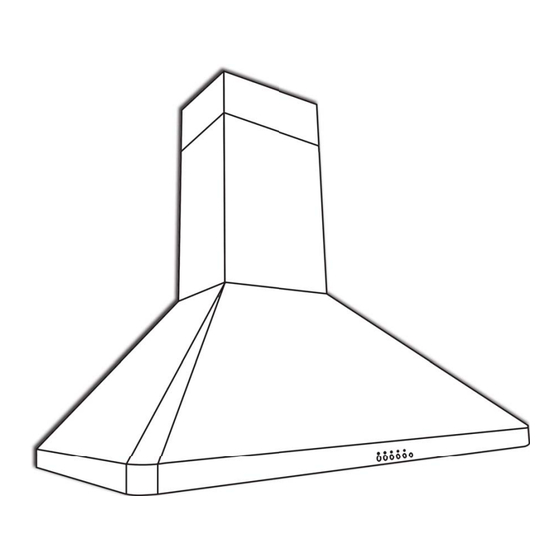
Measurements and Diagrams Installation Overview: ation Overview: Chimney- Qty: 4 PCS mounting bracket Qty: 6 PCS Upper support frame Qty: 4 PCS Upper chimney Back of the range hood Qty: 4 PCS (For sheet rock only) Hood-mounting bracket Round duct (exhaust) Range hood Page 16... - Page 19 • All measurements in parenthesis are in millimeter. • All inch measurements are converted from millimeters, thus inch measurements are estimated. Overall: Page 17...
- Page 20 • All measurements in parenthesis are in millimeter. • All inch measurements are converted from millimeters, thus inch measurements are estimated. Overall without Chiminey: Page 18...
- Page 21 Hood-mounting Bracket: Circuit Diagram: Page 19...
- Page 22 Range Hood Assembly: Description Description Chimney-Mounting Bracket Control Panel Assembly Upper Standard Chimney Processor Board Lower Standard Chimney Baffle Handle Chimney-Mounting Bracket Electrical Box Cover Hood-Mounting Bracket Electrical Box Base Power Cable Halogen Light Transformer Safety Screen Electrical Panel Locknut Control Panel Assembly Panel Squirrel Cage Hood Casing...
- Page 23 Blower Assembly: Description Description Motor Locknut Air Chamber Safety Screen Squirrel Cage Electrical Assembly: Description Description Screws (3/16” x 3/8”) Electrical Panel Electrical Box Cover Capacitor Processor Board Screws (3/16” x 3/8”) Screws (3/16” x 3/8”) Halogen Light Transformer Electrical Box Base Page 21...
-
Page 24: Cleaning
Filters should be cleaned after every 30 hours of use. Replacing Filters: • Should filters wear out due to age and prolonged use, replace with following part number: Product ID: AP238-ACS-SSBF (Available at http://www.euro-kitchen.com) Replacing the light bulb: • This range hood uses halogen bulb: 20W 12V. -
Page 25: Coverage & Exceptions
Damage of product caused by accident, fire, floods or act of God. Euro-Kitchen is not liable for, and does not cover under warranty, any loss of properties or any costs associated with removing, servicing, installing, or determining the source of problems with Euro-Kitchen products. -
Page 26: Disclaimer & Contact Us
Contact Us If you need any assistance, please call us at (510) 266-0099 or email us at sales@euro-kitchen.com. Please have your order number and model of the range hood ready. This information will help us better respond to your re- quest. - Page 27 Your Notes Page 25...
- Page 28 Euro-Kitchen, Inc. 2341 Industrial Parkway West Hayward, CA 94545 Ph: 510.266.0099 Fax: 510.266.6630 http://www.euro-kitchen.com...
Need help?
Do you have a question about the AirPRO 238 Professional Series and is the answer not in the manual?
Questions and answers