Table of Contents
Advertisement
Advertisement
Table of Contents

Related Manuals for Venue thinpar 64

Summary of Contents for Venue thinpar 64
- Page 1 64 OWnEr’S ManUaL www.venuelightingeffects.com...
-
Page 2: Table Of Contents
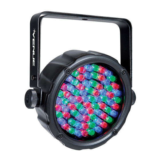
INTRODUCTION The Venue Thinpar 64 is a DMX intelligent LED Par Can. It is lightweight and compact which makes it a great light for Houses of Worship, mobile DJs, clubs and parties. This unit can be used as a stand alone fixture in sound-activated mode, or controlled via DMX controller. -
Page 3: Before You Begin
1. BEFORE YOU BEGIN What iS included • Thinpar 64 • Power Cord • Warranty Card • User Manual unpacking inStructionS Carefully unpack the carton, then check the contents to ensure that all parts are present and have been received in good condition. Notify the shipper immediately and retain packing material for inspection if any parts appear damaged from shipping, or the carton itself shows signs of mishandling. Save the carton and all packing materials. In the event that a fixture must be returned to the factory, it is important that the fixture be returned in the original factory box and packing. -
Page 4: Safety Instructions
• Make sure there are no flammable materials close to the unit while operating. • The unit must be installed in a location with adequate ventilation, at least 20” (50 cm) from adjacent surfaces. Be sure that no ventilation slots are blocked. • Always disconnect from the power source before servicing or replacing the fuse and be sure to replace with same type fuse. • Secure fixture to fastening device using a safety chain. • Maximum ambient temperature is 104° F (40° C). Do not operate the fixture at temperatures higher than this. • In the event of a serious operating problem, stop using the unit immediately. Never try to repair the unit yourself. • Never connect the device to a dimmer pack. • Make sure the power cord is never crimped or damaged. • Never disconnect the power cord by pulling or tugging on the cord. • Never carry the fixture directly from the cord. Always use the hanging/mounting bracket. • Avoid direct eye exposure to the light source while it is on. thinpar 64 users Manual... -
Page 5: Introduction
3. INTRODUCTION control featureS • Static colors and RGB color mixing with or without DMX controller • Built-in automated programs via master/slave or DMX with variable speed • Built-in sound activated programs via master/slave or DMX • Pulse effect with adjustable speed • 3 or 7 channel DMX-512 operation additional featureS • 2.5” low profile design • Power linking: 40 units @ 120V, 60 units @ 230V, 10A circuit max • Double-bracket yoke doubles as floor stand Back panel AUDIO CONTROL SENSITIVITY DISPLAY ADJUSTMENT (see pg 8) (see pg 10) MICROPHONE (see pg 10) CONNECTION JACKS POWER (see pg 8) -
Page 6: Setup
To determine the power requirements for a particular fixture, see the label affixed to the back plate of the fixture or refer to the fixture’s specifications chart. A fixture’s listed current rating indicates its average current draw under normal conditions. Always connect the fixture to a switched circuit. Never connect the fixture to a rheostat (variable resistor) or dimmer circuit, even if the rheostat or dimmer channel is used only as a 0 to 100% switch. Always connect the fixture to a circuit with a suitable electrical ground. poWer linking This fixture contains power linking via the outlet located on the back panel. Please see the diagram below for further explanation. The maximum quantity of fixtures that may be linked is 40 units @ 120V, 60 units @ 230V, 10A circuit max. thinpar 64 users Manual... -
Page 7: Mounting Orientation
Mounting orientation The lightweight ThinPar 64 may be mounted in any position. rigging Be sure that the structure can support the weight of the fixture. Please see the “Technical Specifications” section of this manual for a detailed weight listing. Mount the fixture securely. This may be done with a screw, nut and bolt, or a hanging clamp (not included). The hole in each bracket can fit a 13mm screw or bolt. When rigging, consider routine maintenance and back panel access. Please see the following steps for installation. • If the power link out is intended to be used with multiple fixtures, take into account the length of each power cable, and mount the fixtures close enough to one another to account for this. •... -
Page 8: Signal Linking
Access these functions using the four buttons located directly underneath the LED Control Display. Button function Scrolls through the current operating mode, as well as back out of <Menu> the current menu option <up> Selects increasing advancement in the value <doWn> Selects decreasing advancement in the value <enter> Selects a value and store it to memory thinpar 64 users Manual... -
Page 9: Control Panel Menu Selections
The Control Display shows the current state of the unit. It is used to select the operating mode, as well as the sub-features. For detailed functions, please see the section below. control panel Menu SelectionS Main function SuB-function Selection SuB-Selection inStruction 7 Color Switching 7 Color Fading... -
Page 10: Menu Map
8. Repeat steps 6 & 7 until the desired color is obtained. Press to save the final color setting. This will move <enter> the selection to the following color; however, this is necessary to save the modification. The colors are represented by the following in the menu map: 000-100 = Red ( 000-100 = Green ( 000-100 = Blue ( thinpar 64 users Manual... -
Page 11: Dmx Operation
7. Dmx OPERATION This is the operating mode which will allow for an external DMX controller. You must set the starting address for this mode. If this is your first time using DMX, then it is recommended that you refer to the “DMX Primer” section in the “Appendix” of this manual. 3-CH 7-CH 1. Press until “ ” or “ ” appears on the LED screen. <Menu> 2. Press <enter> d 1-d512 3. -
Page 12: 7-Ch Mode Dmx Operation
Auto snap transition (7 colors) 224 - 255 Sound triggering mode Dimmer 0.0.0. - 255 Intensity: 0% - 100% (RGB/Macro modes) 3-ch Mode dMX operation channel Meaning function 0.0.0. - 255 Dimmer: 0% - 100% green 0.0.0. - 255 Dimmer: 0% - 100% Blue 0.0.0. - 255 Dimmer: 0% - 100% thinpar 64 users Manual... -
Page 13: Appendix
8. APPENDIx dMX priMer There are 512 channels in a DMX connection. Channels may be assigned in any manner. A fixture capable of receiving DMX will require one or a number of sequential channels. The user must assign a starting address on the fixture that indicates the first channel reserved in the controller. There are many different types of DMX controllable fixtures and they all may vary in the total number of channels required. Choosing a start address should be planned in advance. Channels should never overlap. If they do, this will result in erratic operation of the fixtures whose starting address is set incorrectly. You can however, control multiple fixtures of the same type using the same starting address as long as the intended result is that of unison movement or operation. In other words, the fixtures will be slaved together and will all respond exactly the same. Consult the Owner’s Manual to your DMX controller for more information. -
Page 14: Fixture Linking
Use a cable which meets the specifications for EIA RS-485 applications. Standard microphone cables cannot transmit DMX data reliably over long distances. The cable must have the following characteristics: Type: shielded, 2-conductor, twisted pair Maximum capacitance between conductors: 30 pF/ft Maximum capacitance between conductor and shield: 55 pF/ft Maximum resistance: 20 Ohms/1000 ft Nominal impedance: 100 ~ 140 Ohms caBle connectorS Cabling must have a male XLR connector on one end and a female XLR connector on the other end. Do not allow contact between the common and the fixture’s chassis ground. Grounding the common can cause a ground loop, and your fixture may perform erratically. Test cables with an Ohm meter to verify correct polarity and to make sure the pins are not grounded or shorted to the shield or each other. thinpar 64 users Manual... -
Page 15: 3-Pin To 5-Pin Conversion Chart
3-pin to 5-pin converSion chart If you use a controller with a 5-pin DMX output connector, you will need to use a 5-pin to 3-pin adapter. The chart below details a proper cable conversion: 3-pin to 5-pin converSion chart conductor 3-Pin Female (Output) 5-Pin Male (Input) ground/Shield Pin 1 Pin 1 data ( - ) signal Pin 2 Pin 2 data ( + ) signal Pin 3 Pin 3 not used Pin 4... -
Page 16: Technical Specifications
Retailer and manufacturer shall not be liable for damages based upon inconvenience, loss of use of product, loss of time, interrupted operation or commercial loss or any other incidental or consequential damages including but not limited to lost profits, downtime, goodwill, damage to or replacement of equipment and property, and any costs of recovering, reprogramming, or reproducing any program or data stored in equipment that is used with Venue products. This guar- ® antee gives you specific legal rights. You may have other legal rights which vary from state to state. Some states do not allow limitations on how long an implied warranty lasts, so the above limitation may not apply to you. Venue Lighting Effects P.O. Box 5111, Thousand Oaks, CA 91359-5111 www.venuelightingeffects.com All trademarks and registered trademarks mentioned herein are recognized as the property of their respective holders. Made in China. 110.6-9592 thinpar 64 users Manual...
Need help?
Do you have a question about the thinpar 64 and is the answer not in the manual?
Questions and answers