
Related Manuals for Manzanita Micro PFC-50


Summary of Contents for Manzanita Micro PFC-50
- Page 1 PFC-50 & PFC-75 Charger Owner’s Manual Rev 2.1 ©2012 Manzanita Micro LLC The information date is: 02/10/2012...
-
Page 2: Table Of Contents
- Reg Bus Port ~ Basic Info……………………………………………….. 11 - Descriptions of Panel LED Indicators………………………………… 11-12 - Dip Switches……………………………………………………………….. 13 WIRING YOUR MANZANITA MICRO CHARGER……………………….. 14 - Connecting the Charger to the Battery Pack………………………… 14 - Connecting the Charger to the Wall…………………………………… 17 - PFC50 Wiring………………………………………………………………. -
Page 3: Read This First
With such flexibility, the charger is intended to be able to be configured for use in various experimental applications and Manzanita Micro LLC and its employees, contractors and affiliates cannot be responsible for any damages due to any Manzanita Micro product that has been set up by the end user. - Page 4 Manzanita Micro chargers are capable of outputting any charging voltage from 12 to 450 volts DC. It is up to the end user to understand the safe voltage range for their particular battery, cell, battery pack or other energy storage device.
-
Page 5: General Overview
Every model is user adjustable to charge batteries from 12 to 450 Volts DC. The PFC-50, PFC-50B and PFC-75 are all power factor corrected. The PFC-75 comes standard with an AC input current display and rear panel mount Anderson Power Pole connections. -
Page 6: Key Features List
12 to 450 volts •Up to 18,000 watts of power from a unit that weighs less than 50 lbs (22kg) •Reg bus port for easy integration with Manzanita Micro BMS (also compatible with other Battery Management Systems) •Self regulating thermal protection... -
Page 7: Dimensions And Specifications
Power Consumption : Up to 12.0kW ~ PFC-50 and PFC-50B / 18.0kW ~ PFC-75 The 50 in PFC-50 is indicative of the number of amps that the charger is rated to draw from the AC line. A PFC-75 can draw up to 75 amps. Unlike some other chargers, this is the rated continuous load and all units are thoroughly tested to their rated limits before leaving Manzanita Micro. -
Page 8: Charger Operation
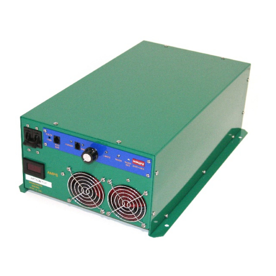
best and stainless steel or other quality plating is preferable to decrease corrosion. Charger Operation figure 02. Charger Layout (see final section for new 8A layout) Turning the Charger On and Off There is an ON/OFF Breaker to the left of the blue user control panel at the top of the charger. -
Page 9: Volts Trim ~ Adjusting The Peak Charging Voltage Limit
This controls the peak DC voltage ceiling that the charger will allow the batteries to reach before limiting the current. Unless specified otherwise, the voltage limit is specifically calibrated and set by Manzanita Micro to 191 Volts (for a 156V nominal pack.) In the event that adjustment is desired, please follow the instructions below. - Page 10 VOLTS TRIM CALIBRATION: Final tuning is best accomplished when the battery pack is fully charged. The lower the state of charge, the more the user will need to monitor and adjust the unit during the first charge cycle. Turn the amps knob all the way down (full counterclockwise). Make sure the charger is plugged into the battery pack and that there are no open breakers or open fuses in the DC battery circuit.
-
Page 11: Reg Bus Port ~ Basic Info
If this indicator stays on, turn down the AMPS knob immediately, turn off the charger’s breaker switch and consult Manzanita Micro or a qualified service technician. This LED could indicate an over voltage or over temperature condition. It could also be indicative of an open circuit condition in the pack. - Page 12 “AMPS” Knob The AMPS knob allows the user to adjust how much current the charger will move. If the vehicle is always plugged in to the same circuit this shouldn’t need any adjusting but if the user were to have it set at 35 amps and then plug into a 15 amp 120V outlet it will quickly open a circuit breaker or fuse on the AC line.
-
Page 13: Dip Switches
If the switch is at ‘0’ then the timer will time out instantly - do not use this setting. (‘0’ is the 3-o-clock position when viewed from the front). If the switch is at ‘1’ it will go for 15 minutes before completely cutting back power. Each additional tick after ‘1’ adds 10 more minutes to the charge cutback time. -
Page 14: Wiring Your Manzanita Micro Charger
For rear mount connections please refer to the PFC-75 wiring section that follows this one. Looking at the front of a pre-2011 PFC-50 or PFC-50B charger, you will see that the lower DC output cable has a Blue SB-175 Anderson connector on it. - Page 15 Use a digital volt meter to double check that the polarity in the plug is correct and then plug the battery pack SB-175 into the DC output SB-175 coming from the PFC charger. Now the charger is connected to the pack and you are ready to hook up the charger’s input power. figure 06: PFC-50 Plugs...
-
Page 16: Pfc75 Wiring
PFC-75 Pack Wiring Looking at the back of a PFC-75 charger or post 2011 PFC-50, you will see that there are five individual Anderson Power Pole connectors. There is a black and a red one next to each other on the top which is the DC output end of the charger. For your convenience a red and a black Power Pole connector have been included with your PFC-75. -
Page 17: Connecting The Charger To The Wall
Connecting the Charger to the Wall Looking at the front of a pre-2011 PFC-50 the charger you will see that the top cable is labeled AC and it is the incoming power for the charger. Looking at the rear of a PFC-75 or other late model charger you will see 3 Anderson Power Pole connectors beneath the two DC output connectors. - Page 18 “Amps” knob on the front. Turn this knob up or down depending on the amperage available from the outlet. With the “Amps” knob in the most clockwise position a PFC-50 can draw up to 50 amps and a PFC-75 can draw up to 75 amps.
-
Page 19: Running Your Pfc Charger On Dc Instead Of Ac
Running Your PFC Charger on DC instead of AC You may have heard that Manzanita Micro chargers can run from both AC and DC power. This is true under the right circumstances; in fact the PFC40HM is designed to run on both AC and DC in the Pi Prius conversion kits. -
Page 20: 120V Standard Adapter Drawing For Pfc50 & Pfc75
08. PFC-50 Adapter Wiring... -
Page 21: Reg Bus Wiring & Pin-Out Info
Reg Bus Wiring The Reg Bus Interface: The REG BUS communicates to the charger when any BMS regulators are regulating and also if any regs are too hot. The charger uses this information to determine when to turn down the charge current and when to turn off the charger. The interface contains six wires connected with their respective pins as follows: 1. -
Page 22: Reg Bus Cable Construction
Adding airflow across the regulators will dramatically help cooling the regs and speed up charge equalization. NOTICE! Manzanita Micro strongly advises air cooling of the battery regulators for maximum dissipation capability and longevity of the reg. For more information on regulator cooling see the appropriate Manzanita Micro regulator manual for your system. - Page 23 figure 09. Correct RJ Cable Orientation Step 6: Double check that the blue wire is to the right side with the tang down and then take the RJ crimping tool in your right hand. With your left hand push the cable with un-crimped plug into the 6-pin die on the crimping tool. Step 7: While using your left hand to make sure that the RJ cable is firmly held all the way into the connector, squeeze the crimping tool all the way with your right...
-
Page 24: New 8A Control Board Additional Features
10. Side View of Proper RJ Cable New 8A Control Board Additional Features Manzanita Micro improved the original charger control interface board and began integration into production models in mid 2010. If your charger is equipped with the new control board it will be evident by the new front faceplate which has an extra 4 pin RJ port in between the ‘POWER’... - Page 25 11. New 8A Control Board Exposed View REG BUS ADJUSTMENT THRESHOLD MAIN VOLTS TRIM CHANNEL A (PEAK CHARGING VOLTAGE) ORIGINAL REG BUS PORT FOR MANZANITA MICRO BMS AUTO RESTART THRESHOLD OPTIONAL VOLTS TRIM CHANNEL B OPTIONAL VOLTS TRIM CHANNEL C...
-
Page 26: Ac Line Power Meter Options
As of January 1, 2011 Manzanita Micro includes a regular AC current meter built into the front of all PFC-50 and PFC-75 chargers. This standard display allows the user to see in real time exactly how many amps the Manzanita Micro charger is drawing from the AC power source that it is plugged into. -
Page 27: Contacting Manzanita Micro
For more information visit: www.manzanitamicro.com Or for technical questions or other inquiries: Manzanita Micro Rich Rudman PO Box 1774 Kingston, WA 98346 Phone: 360-297-1660...
Need help?
Do you have a question about the PFC-50 and is the answer not in the manual?
Questions and answers