Table of Contents
Advertisement
Quick Links
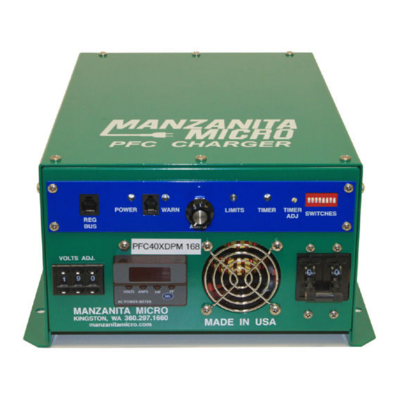
PFC-20, PFC-30 &
PFC-40 Charger
Owner's Manual
Rev 3.1
©2013 Manzanita Micro LLC
The information date is: 06/07/2013
Manzanita Micro reserves the right to alter product offerings and specifications at any time without notice, and is not
responsible for typographical or graphical errors that may appear in this document.
1
Advertisement
Table of Contents


Need help?
Do you have a question about the PFC-20 and is the answer not in the manual?
Questions and answers