Table of Contents

Related Manuals for Yard Tuff SP-48

Summary of Contents for Yard Tuff SP-48
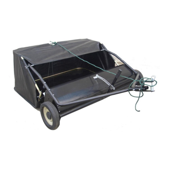
- Page 1 48” Sweeper OWNER’S MANUAL WARNING: Read carefully and understand all ASSEMBLY AND OPERATION INSTRUCTIONS before operating. Failure to follow the safety rules and other basic safety precautions may result in serious personal injury. Item# SP-48 11022010...
-
Page 2: Technical Specifications
Thank you very much for choosing this product! For future reference, please complete the owner’s record below: Model: ___SP-48__________ Purchase Date: _______________ Save the receipt, warranty and these instructions. It is important that you read the entire manual to become familiar with this product before you begin using it. This product is designed for certain applications only. -
Page 3: Work Area
WORK AREA • Keep work area clean, free of clutter and well lit. Cluttered and dark work areas can cause accidents. • Keep children and bystanders away while operating a sweeper. Distractions can cause you to lose control, so visitors should remain at a safe distance from the work area. •... -
Page 4: Carton Contents
CARTON CONTENTS Hitch Tube, R.H Hitch Tube, L.H Height Adjustment Assembly Hitch Bracket (Straight) Hitch Bracket Sweeper Housing Assembly Front Support Rod Bag Arm Tube (2) Bag Frame Strap Hopper Support Rod (2) Lower Hopper Side Tube (Right) Lower Hopper Side Tube (Left) Upper Hopper Side Tube (Right) Upper Hopper Side Tube (Left) Rear Hopper Tube (2) - Page 5 REF. QTY. DESCRIPTION REF. QTY. DESCRIPTION Hex Bolt M8x75 Angle Bracket Hex Bolt M8x55 Adjustable Pole Spacer Hex Bolt M8x40 Hitch Spacer Hex Bolt M6x40 R Pin Ø3 Hex Bolt M8x20 R Pin Ø2 Hex Bolt M8x16 Clevis Pin Ø9.5x25 Nylon Lock Nut M8 Clevis Pin Ø6x37 Nylon Lock Nut M6...
- Page 6 ASSEMBLY All loose parts are shown on page 2. Hardware in the parts bag are shown on page 3. Remove the hardware pack and all loose parts from the carton and verify that all the parts and hardware shown on pages 2 and 3 are included. Note: Right hand (R.H.) and left hand (L.H.) are determined from the operator’s position while seated on the tractor.
- Page 7 (Figure 3) Fasten the hitch tubes together using two M8 x 75 hex bolts (A), and M8 nylon lock nuts (G). Do not tighten yet. If your tractor hitch has 10” to 13” ground clearance refer to figure 4. If your tractor hitch has 8” to 10”...
- Page 8 (Figure 6) Assemble the height adjustment handle to the height adjustment tube as shown in figure 6. Use two M8×40 hex bolts (C) and M8 Nylon Lock nut (G). Do not tighten yet. (Figure 7) Insert a M8×20 hex bolt (E) through the angle bracket. Assemble onto the bolt (in order) the adjustable polo spacer (L), the height adjustment strap, a big flat washer Ø8 (J) and a M8 nylon lock nut (G).
- Page 9 (Figure 8) Position the height adjustment handle side to side so that the wear washer and big flat washer can fit between the handle and the height adjustment strap. Tighten the nuts securing the height adjustment handle. (Figure 8) Insert the carriage bolt M8×30 through the height adjustment handle. Assemble onto the bolt, in order, the bolt, the height adjustment handle, the wear washer, the height adjustment strap, the wear washer, the big flat washer, and the plastic knob.
- Page 10 ASSEMBLY OF HOPPER BAG (Figure 10) Turn the rear hopper tube so that the brace holes in the middle of the tube face down. Slide the tube through the two loops sewn to the top rear seam inside the hopper bag. (Figure 11) Insert the two upper hopper side tubes through the stitched flaps on each side of the hopper bag.
- Page 11 (Figure 12) Turn the second rear hopper tube so that the brace holes in the middle of the tube face up. Assemble the ends of the rear hopper tube onto the ends of the lower hopper side tubes. Fasten together using plastic plugs. (Figure 13) Place the assembled lower hopper tubes into the bottom of the hopper bag (Figure 13) Attach the ends of the lower hopper side tubes to the inside of the upper hopper side tubes using two Ø9.5 x 25 clevis pins (P) inserted from the inside, and two Ø3 R pins (N).
- Page 12 (Figure 14) Insert the bag frame strap into the stitched sleeve along the front edge of the bag bottom. (Figure 14) Assemble the bag frame strap to the lower hopper side tubes using two Ø6x37 clevis pins (Q) and Ø2 R pins (O). Ø2 R PIN (O) (Figure 15) Secure the bag corners around the lower hopper side tubes by snapping the bag flaps to the bag bottom on both sides.
- Page 13 IMPORTANT: Do not over bend the support rods during the following step. Over bending will cause the steel rods to lose supporting tension. (Figure 16) Tip the hopper onto its back to assemble the two hopper support rods. Place the ends of each rod into the upper and lower rear hopper tubes, bending the rod just enough to fit into the holes in the tubes.
- Page 14 (Figure 18) Secure the rope to the top center of the hopper bag frame. (Figure 19) To assemble the hopper bag to the sweeper, slide the ends of the bag arm tubes into the ends of the sweeper’s hitch tubes and secure with two Ø6×42 clevis pins (R) and Ø2 R pins (O). Page of 20...
- Page 15 ATTACHING SWEEPER HITCH TO TRACTOR (Figures 20, 21, 22) 1. Place the tractor and sweeper on a flat level surface. 2. Set the sweeper height adjustment handle to about the middle of its adjustment range. 3. Attach the sweeper hitch brackets to the tractor hitch, arranging the 3/4” spacers so that the bottom of the sweeper bag is approximately level and 5”...
- Page 16 Page of 20...
-
Page 17: Operation
OPERATION WARNING: Do not permit children to operate sweeper. WARNING: Never attach the hopper rope to any part of your body or clothing! Never hold onto the rope while towing the sweeper! MAINTENANCE • Maintain your sweeper. It is recommended that the general condition of any sweeper be examined before it is used. -
Page 18: Diagram & Parts List
DIAGRAM & PARTS LIST Page of 20... - Page 19 Ref # Description Qty. Ref # Description Qty. Hitch Tube, Right Side Pinion Gear R.H. Hitch Tube, Left Side Pinion Gear L.H. End plate, Right Side Hex Bolt M5x25 End plate, Left Side Dust Cover Assembly Wrapper Hopper Frame Tube (Rear) Hex Bolt, M6×12 Upper Hopper Frame Tube (L.H) Hex Bolt, M5×12...
-
Page 20: Warranty
WARRANTY One-year limited warranty PO BOX 202 Hopkins, MN 55343 Made in China Page of 20...
Need help?
Do you have a question about the SP-48 and is the answer not in the manual?
Questions and answers
Where can i purchase hopper bag for yard tuff sp-48t