Amtrol GUARDIAN CP DC2 Installation & Operation Manual
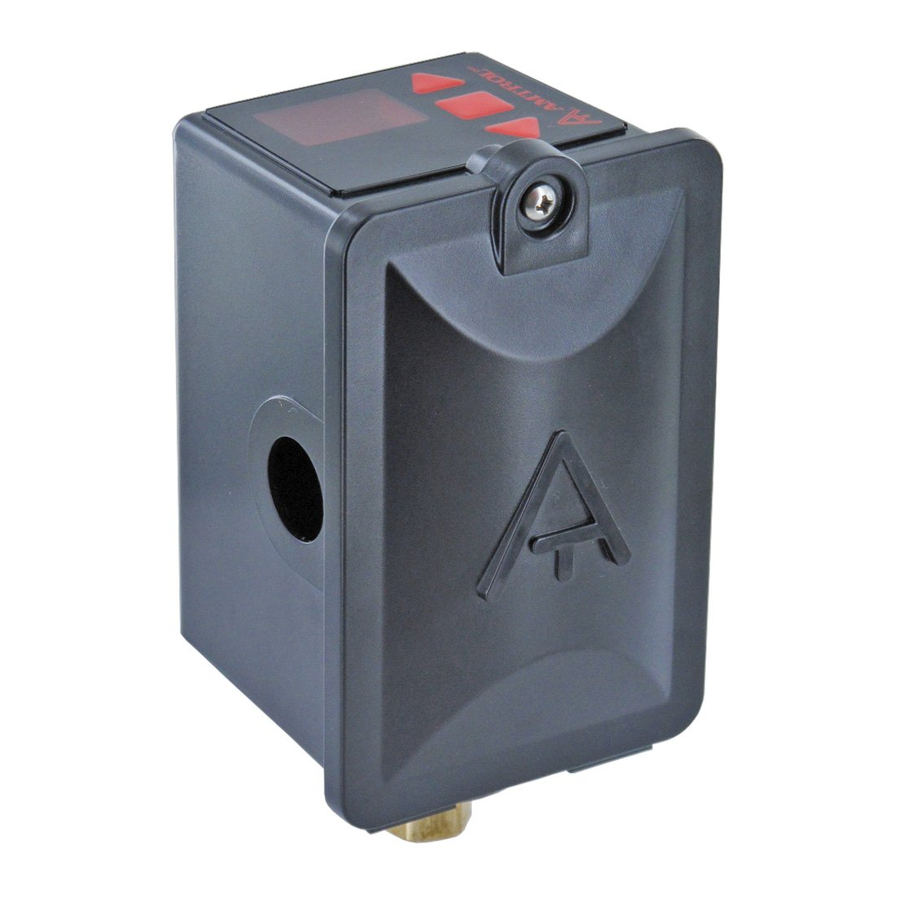
Digital pump control
Hide thumbs
Also See for GUARDIAN CP DC2:
- Installation and operation manual (4 pages) ,
- Installation & operation instructions (13 pages)
Advertisement
West Warwick, Rhode Island 02893
Your DC2 DIGITAL CONTROL has been carefully assembled and factory tested. To enjoy
the full service this unit can provide, you should read and follow all of the instructions in this
manual. When all installation steps have been completed, make sure you also follow the
enclosed post-installation and startup checklists before using your AMTROL
should also read carefully the sections describing proper product maintenance and follow
the required procedures as you use your DC2 DIGITAL CONTROL. Keep this manual with the
product. This manual may become out-of-date by later amendments. Check our web site,
www.amtrol.com or ask your AMTROL
THIS IS THE SAFETY ALERT SYMBOL. IT IS USED TO ALERT YOU TO
POTENTIAL PERSONAL INJURY AND OTHER HAZARDS. OBEY ALL
SAFETY MESSAGES THAT FOLLOW THIS SYMBOL TO REDUCE THE
RISK OF POSSIBLE INJURY AS WELL AS PROPERTY DAMAGE.
INSTALLER: LEAVE THIS MANUAL WITH THE OWNER
Part # 9046-0001 (09/10)
Guardian CP
Digital Pump Control
supplier for any updates relating to your product.
®
INSTALLATION, OPERATION
INSTRUCTIONS
™
1
& MAINTENANCE
Model DC2
product. You
®
Patent Pending
Advertisement
Table of Contents

Related Manuals for Amtrol GUARDIAN CP DC2


Summary of Contents for Amtrol GUARDIAN CP DC2
- Page 1 When all installation steps have been completed, make sure you also follow the enclosed post-installation and startup checklists before using your AMTROL should also read carefully the sections describing proper product maintenance and follow the required procedures as you use your DC2 DIGITAL CONTROL.
-
Page 2: Installation Instructions
INSTALLATION INSTRUCTIONS Unit Must be Installed by a Qualified Professional PLUMBING CONNECTION 1. Select a location for the DC2. The DC2 should be mounted near the pressure tank or pump, depending upon the installation LOCATE THE DC2 FOLLOWING ALL LOCAL CODES. DO NOT LOCATE THE UNIT WHERE IT CAN BE AFFECTED BY FLOODING. - Page 3 4. Loosen the screw on the cover of the controller and remove the plastic cover, exposing the wiring pigtails. (When reassembling cover, do not over-tighten screw.) 5. The wire conduit hub is to be connected to the conduit before the hub is connected to the enclosure.
- Page 4 START UP BEFORE CONTINUING, CHECK FOR OPEN DRAIN VALVES OR OTHER SOURCES OF FLOODING BEFORE STARTING UNIT. 1. Prime pump if necessary and adjust tank precharge to manufacturer’s recommendation for intended pressure range. The factory DC2 setting is 40 psi cut-in and 60 psi cut-out.
-
Page 5: Troubleshooting
Problem No power Display will not Improper wiring illuminate Improper voltage Differential attempted is below 10 psi or above 55 psi HI or LO setting will Minimum cut-in reached not change Maximum cutout reached HI setting greater than pump rating Insufficient prime (above ground Pump will not reach pumps) - Page 6 GENERAL SAFETY INFORMATION WARNING: REVIEW ALL GENERAL SAFETY INFORMATION PRIOR TO INSTALLATION. READ CAREFULLY THE PRODUCT INSTALLATION, OPERATING AND MAINTENANCE INSTRUCTIONS. FAILURE TO FOLLOW THE INSTRUCTIONS AND WARNINGS IN THE MANUAL MAY RESULT IN SERIOUS OR FATAL INJURY AND/OR PROPERTY DAMAGE, AND WILL VOID THE PRODUCT WARRANTY. THIS PRODUCT MUST BE INSTALLED BY A QUALIFIED PROFESSIONAL.
- Page 7 Please read the entire owner’s manual and installation instructions before installing our new AMTROL reference. Current copies of the Product manual can be viewed at www.amtrol.com. Use proper safety equipment when installing. You must comply with all plumbing and electrical codes.
- Page 8 What AMTROL Will Do If You Have a Covered Warranty Claim? In the event of a breach of the foregoing warranty, AMTROL will at its option either make repairs to correct any defect in material or workmanship or supply and ship either new or used replacement parts or products. AMTROL will not accept any claims for labor or other costs.
Need help?
Do you have a question about the GUARDIAN CP DC2 and is the answer not in the manual?
Questions and answers