Table of Contents
Advertisement
Installation Manual
User Guide
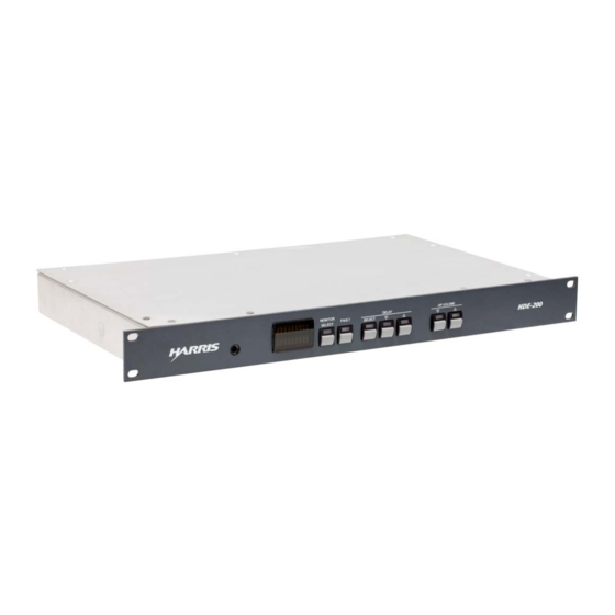
HARHDE200 FlexStar HDE-200 Embedded Exporter
HARHDE200-PROFAN Profanity Delay Upgrade
HARHDE200-PPM Arbitron PPM Interface Upgrade
HARHDE200-PROF/PPM Combined Upgrade
Support phone: 217.222.8200 • e-mail: tsupport@harris.com
Internet: http://ecustomer.broadcast.harris.com
&
75-56
Revision F • 3/12
BROADCAST COMMUNICATIONS DIVISION
Advertisement
Table of Contents

Related Manuals for Harris FlexStar HDE-200

Summary of Contents for Harris FlexStar HDE-200
-
Page 1: Installation Manual
Installation Manual & User Guide HARHDE200 FlexStar HDE-200 Embedded Exporter HARHDE200-PROFAN Profanity Delay Upgrade HARHDE200-PPM Arbitron PPM Interface Upgrade HARHDE200-PROF/PPM Combined Upgrade 75-56 Revision F • 3/12 BROADCAST COMMUNICATIONS DIVISION Support phone: 217.222.8200 • e-mail: tsupport@harris.com Internet: http://ecustomer.broadcast.harris.com... - Page 2 H A R R I S C O R P O R A T I O N Revision F • 3/12...
-
Page 3: Table Of Contents
2.3.2 GPS Antenna Connection ....2-4 5 SERVICE 2.3.3 Audio Connections ......2-5 2.3.4 HDE-200 Sample & Bit Rate ... 2-6 5.1 Parts and Repair Services ..... 5-1 2.3.5 S/PDIF Connections ......2-6 5.1.1 Parts Ordering & Repair Information 5-1 2.3.6 Using a Studio Remote Panel ... -
Page 4: Ce Declaration Of Conformity
Equipment Class: 99 1440 Model Numbers: I the undersigned, hereby declare that the equipment specified above, conforms to the above Directive(s) and Standard(s). Place: Harris Corporation - Mason, Ohio USA Signature: Full Name: Ted Staros Position: Director - Studio Products Development... -
Page 5: Hazard/Warning Label Identification
WARNING: THIS PRODUCT USES A UL-LISTED 5 VDC POWER SUPPLY. IF REPLACEMENT IS REQUIRED, USE ONLY A HARRIS PRE50-26 POWER SUPPLY. NOTE: This equipment has been tested and found to comply with the limits for a Class A digital device, pursuant to part 15 of the FCC Rules. -
Page 6: Manual Revision History
Revision E - Updated specifications for Clock Outputs, IP addresses, added networking notes Revision F - New Front Panel design changes, IP addressing changes, operational changes reflected for ECC app version 1.2.16 and HDE-200 firmware version 4.3.2.6 Trademark Information FlexStar and HDE-200 are proprietary trademarks of Harris Corporation. -
Page 7: Product Overview
Radio Exciter like the Harris HDX-100 Exciter. allow the incoming or output audio to be moni- The HDE-200 can be located in a studio or in a tored via a level meter and front panel headphone terminal room—as opposed to having to be co- jack. -
Page 8: Upgrades
There are two AES digital audio inputs on the The Profanity Delay kits add a second delay HDE-200 ( Main Delay In and MPS Audio In ). function to the HDE-200—with remote studio The Main Delay In put is typically used for the... -
Page 9: Specifications
4 lbs Internal Sample Rate: 44.1 kHz AES Input Compliance: 16-bit or 24-bit (24-bit Harris Corporation reserves the right to change inputs are truncated to 16-bits) specifications without notice or obligation. Input Signal Format (Main Delay In, MPS Audio In): 110 ohm AES (S/PDIF accepted, 0.3 Vpp min) -
Page 10: Warranty
Harris does not warrant nor guarantee, and is region of Customer’s site, so as to minimize not responsible for: freight and duty. Harris bears the risk of loss or damage while the Equipment (or part thereof) is Defects, failures, damages or performance... - Page 11 Customer, Customer may, as its exclusive remedy, and repair the Equipment. obtain a refund of the fees paid to Harris under the applicable Order for such Services. Equipment built to Customer’s specifications that are later found not to meet Customer’s needs or expectations.
- Page 12 1 Product Overview or Licensed Program that (A) has been altered or interpretation of this Agreement shall be in the modified, except by Harris; (B) has not been courts with the appropriate jurisdiction located installed, operated, repaired, or maintained in in Orlando, Florida, and each party irrevocably accordance with instructions supplied by Harris;...
-
Page 13: Hardware
Hardware 2.1.1 AUDIO CONNECTIONS he HDE-200 can be mounted in a studio, There are four AES-3 balanced digital audio connections using XLR-type connectors. All con- terminal room, or transmitter facility. It requires one form to standard AES-3 (AES/EBU) digital wir- ing practices (3 volt signals, 110 ohm, balanced rack unit (1RU) of space. -
Page 14: Connection Summary
Importer, an HD Radio Exciter (or digital STL), 2.1.2 CONNECTION SUMMARY and an admin computer can directly connect to A summary of the HDE-200’s audio, network- the HDE-200. ing, and logic connections is shown below. In ad- The HDE-200 can, alternately, connect through... -
Page 15: Optional Upgrade Kits
10.10.10.10), the other for the iBiq- delay is completely separate from—and does not uity HD Radio DSP board (default: affect, the Diversity Delay built into the HDE-200. 10.10.10.22). Do not connect any The Arbitron PPM Encoder Interface connects CAT-5 cables to the HDE-200’s three... -
Page 16: Connections
For signal shielding, connect the digital audio page. Replace the top cover, then rack mount the cable shields at both the HDE-200 and the inter- HDE-200 using four rack screws. connecting equipment ends when all system com-... -
Page 17: Audio Connections
Main Delay In . You must then use in order to connect it to the HDE-200. the ECC app to change the HDE-200 to use only Other GPS antennas may work with the HDE- the Main Delay In connector (otherwise there will 200, but they must use +5 VDC for power (many be an Audio Fault indication). -
Page 18: Sample & Bit Rate
16 most significant bits. the XLR shell are tied directly to chassis ground. 2.3.5 S/PDIF CONNECTIONS If the HDE-200 power is lost, the Main Delay In signal is relay switched to directly connect to Digital devices with S/PDIF unbalanced out-... -
Page 19: Using A Studio Remote Panel
A 44-pin D-Sub connector ( Remote I-O Logic ) Remote I-O Logic Signal Summary allows remote control and delay status indication for the HDE-200. It’s typically wired to a Logic Inputs studio-mounted remote panel like the six-button Each input section must be enabled by Harris Control Panel (Harris p/n PRE99-1212). - Page 20 Profanity Delay Dump (-) Ramp Complete Tally, Diversity Other Enable (+) Diversity Delay Tally Common 18 Ramp Up Tally, Profanity Warm Boot HDE-200 (-) Spare Ramp Down Tally, Profanity Ballpark Mode (-) Notes: Optional Profanity Delay activation kit required to use Profanity Delay Logic.
-
Page 21: Hd Radio Exciter Connections
Exciter used does not have an AES input, an AES/ nize the Exciter to the HDE-200 Exporter con- EBU-to-analog signal converter is required. nect the 10 MHz clock output from the HDE-200 to the Exciter’s 10 MHz Reference Input. H A R R I S C O R P O R A T I O N Revision F •... -
Page 22: Network Connections
Diversity Delay and Profanity delay settings puter can be networked with the HDE-200 and and the other HDE-200 operational settings. the ECC app used to set the various HDE-200 The admin computer can be any laptop or desk- configurations directly over the network. These set-... -
Page 23: Software
ECC user using your app). The ECC app is supplied with each HDE-200 facility’s computer login names and passwords. on a USB flash drive. The ECC app can also be down-... - Page 24 HDE-200 Exporters. settings, if active will be compromised. The table illustrates the specific control permis- sions for the four HDE-200 User Groups and the No Credentials user. Note that you do not have to H A R R I S C O R P O R A T I O N Revision F •...
-
Page 25: Installing The Ecc App
App Note AN10-02 ECC & Windows 7 (in- staller window. cluded as Appendix A) for installation tips per- taining specifically to Windows 7. Locate the HDE-200 installation file on the USB flash drive (F:\Software_Install_Pkg\ Harris\Exporter Control Center\72- 1441rN_ECC_ Installer_ V1.2.16.msi) Launch the installation file by double click- ing the .msi file. - Page 26 3 Control Center Software Groups window. T ype in the new users’ Win- To add or remove users from an HDE-200 user group, right click on the My dows login names in the Enter the object Computer icon and select Manage .
-
Page 27: Starting The Ecc App
Alternately, use the Windows Programs menu name is valid, the displayed name will auto- matically update to append the local com- to start the ECC app: Start > Programs > Harris Corp > FlexStar > HDE-200 Control Center . puter... - Page 28 200 and close the window. dress of 10.10.10.2. Directly connect the computer The selected HDE-200’s current status and con- to port 1 on the new HDE-200. Then select the figuration information is transferred to the ECC new HDE-200 in the Device > Select Device app.
- Page 29 Site Location could iden- this page. These settings are typically tify the city, if the HDE-200 is remotely ac- changed to fit into the facility’s network. cessed on the same subnet, or give its spe- •...
- Page 30 With the USB flash drive inserted into the 3. Unidirectional Subnet Broadcast (allows USB port on the HDE-200, press the multiple Exciters to be fed from this HDE-200 over any type of non-routed path) RESET PROCESSOR button on the rear -Enter the Exciter Address, but use .255 in the last octet...
-
Page 31: Configuration
Backing up the New Configuration Files When the direct connection method is used to update the HDE-200 files, follow steps 1 and 2 in order to write a MAC address-named folder from the updated HDE-200 to the USB flash drive. Use Windows Explorer to then backup that folder to the admin computer. -
Page 32: Delay Control Menu
Up to twelve and half seconds of Diversity De- and silence (like spoken word) instead of lay can be set in the HDE-200. But before one music so that the delay or time difference adjusts the Diversity Delay setting, Enable Blend between the two signals is most easily seen. - Page 33 Delay Value and other settings in this window to To more precisely adjust the Diversity Delay, the nonvolatile memory of the HDE-200 and to view the two signals on a dual trace oscilloscope close the window.
-
Page 34: Profanity Menu
Profanity Menu Items nal. Since Enable Blend is normally checked, you should ensure that it is checked prior to setting The HDE-200 Exporter has an optional feature the Diversity Delay. that can provide up to thirty-five seconds of pro- To set the Enable Blend option, click on the De- fanity delay protection. - Page 35 3 Control Center Software Delay Management Section The Total Profanity Duration and the Dump Du- ration are displayed in seconds.milliseconds. There is some interaction between the two controls since adjusting the Total Profanity Duration can affect the Dump Duration since the maximum Dump Duration is equal to the setting of the Total Pro- Profanity Duration Slider Bar fanity Duration.
-
Page 36: System Menu
The lower section of this window is where the entries used by the Station Information Service Transport Data (SIS Data) are entered. Note that the current HDE-200 firmware release is in com- pliance with NRSC document SY_IDD_1020s, Rev F. The Country Code is entered into the Country Code entry box. - Page 37 3 Control Center Software 3.5.5.2 Station Information Service in the first payload of a block leaving the second payload of that block empty. Click System > Station Information Service... There are a few arcane restrictions regarding to open the SIS data schedule window. Ten SIS messages are available for scheduling, as shown the placement of payloads beyond the above de- in the following illustration.
- Page 38 To summarize, here are some SIS guidelines: the Remote I/O Logic connector on the rear panel • Message latency is managed though of the HDE-200 (page 2-7 has details on using repetition this connection). Uncheck Enable Studio Interface • Keep your messages as short as practical to disable this connection.
- Page 39 Check this selection to invert the signal polarity complete. This method is the way all other of the analog signal path within the HDE-200 in manufacturer’s exporter devices behave during the unlikely event there is an unresolvable polar- Diversity delay alterations.
- Page 40 Network settings in the ECC app, and for updat- grade features have been enabled. Enabling the ing the HDE-200 using a USB flash drive was de- features is done by installing one of the iButton scribed earlier in this chapter.
- Page 41 Exporters, and Exciters in the system. GPS Settings Window The Current Coordinates section lists the lati- tude, longitude, and altitude of the HDE-200 along with the number of satellites that the GPS receiver has detected. Clicking the Map button will dis- play—provided the PC running ECC has Internet...
- Page 42 There are a few grey areas here: Arizona The update process is comprehensive, updat- broadcasters typically leave this box unchecked ing the CPU, the DSP board, and the HDE-200 since Arizona does not observe DST, whereas firmware in one procedure to avoid the complica- Indiana has worked out most of its DST mess: http://en.wikipedia.org/wiki/Time_in_Indiana.
- Page 43 0.0 seconds (0% ramp), reset the the FlexStar devices then the ECC app will not HDE-200 by pressing the rear panel re- see the HDE-200. Thus, this window is the first cessed button: RESET PROCESSOR. The place to look if you cannot establish a connection HD Radio signal will be interrupted but the to the HDE-200.
-
Page 44: Help Menu
There are two options under help: About and Several software utilities, app notes, and other Check for Updates. Selecting About lists the ver- files are provided on the HDE-200 USB flash drive. sion of the ECC app. Copy these to the admin computer for reference. -
Page 45: Using The Hde-200
DSP board. Note The front panel controls on the HDE-200, that MPS In will not be available if the HDE-200 shown below, allow engineers to monitor various is set to use a common input (Main In) as the... -
Page 46: Delay Status & Control
The Fault LED blinks to indicates a fault con- is shown: DVRSTY DLY (for the Diversity Delay) dition in the HDE-200. Press the Fault button to or PRFNTY DLY (for the Profanity Delay). The change the display to show the fault. Alarm ap- bottom row bargraph indicates the delay status—... -
Page 47: Using The Ecc App
HDE- HDE-200 at the top of the window, above the menu 200 User, and they start the ECC app they will items. When first opened (No Device) will be have No Credentials access. -
Page 48: Audio Metering
Pre Delay, shows the AES digital audio signal vice) displays the audio levels for the MPS Audio as it enters the HDE-200 on the MPS Audio In - Input (Pre Delay) or the audio going to the iBiq- uity DSP board (Post Delay). There is no meter put. -
Page 49: Diversity Delay Control
If the blue Peak indicators regularly turn on, the progressing from left to right as the delay increases. signal level feeding the HDE-200 is too hot. Also, the amount of delay in seconds and the per- centage completion begin to increment. While the 4.2.2 DIVERSITY DELAY CONTROL... -
Page 50: Profanity Delay Control
Total Profanity Duration. The relative length In some cases these faults will also be indicated of the bar corresponds to the percentage comple- on the front panel of the HDE-200, blinking the tion of the delay. The bar color turns from red to Fault LED. - Page 51 4 Using the HDE-200 GPS Lock Status Indications ARB MPS = Arbitron PPM Encoder audio for the HD Radio signal: white (PPM option not ac- tive); green (has AES clock); red (no AES clock detected) UP LOS = status of service to HD Exciter...
-
Page 52: Service
Harris product num- ber when ordering. A list of HDE-200 part and vides technical information on the HDE-200 along product numbers is on page 5-2. Some parts may... - Page 53 95-1440 Interface Controller PWA revision. These parts will require a product number 99-1815 Linux CPU (assigned by the Harris parts department) before 99-1820 HD Radio DSP PCA they can be sold as a replacement part. 99-1811 GPS Antenna, Trimble Bullet III...
-
Page 54: Upgrade Kit Parts
U14, U15, U17, U32, U38, U39, U40, and (HARHDE200-PROF/PPM) U41 to derive the four supply voltages (+1.2, +1.8, Harris # Description or Use Qty. +3.3 and +5 volts) used in the HDE-200. 21-801-3 iButton (PPM & Profanity Delay) 1 71-1441 Installation documentation 5.2.1 Interface Controller... - Page 55 The 10 MHz clock a specific code to unlock output (on J11) is used optional features on the to synchronize an HD HDE-200. The iButton Radio Exciter, when uses +3.3 volts and must it’s co-located with the be installed for the op-...
- Page 56 (J2) signal goes through a relay (U28) which couples the signal, through relay U29, to the Main The Front Panel Display board connects to the Delay Out (J4) whenever the HDE-200 is Interface Controller using a 30-conductor ribbon unpowered. cable that carries +5 volts and various control sig- Each digital input, after being unbalanced by nals to and from the display.
-
Page 57: Troubleshooting
Linux CPU, which controls audio routing The CPU also has a USB controller (Host 2.0 through the HDE-200, or the HD Radio DSP compatible). USB power is supplied by U41 on board have hung up and will need to be reset. - Page 58 ) or the pop-up window does not appear, then the default setting of 239.255.255.1, port the Windows Firewall configuration will have to 50010 in the ECC app or on the HDE-200 be manually changed. Open Windows Firewall device. For most installations the default ( Start/Settings/Control Panel/Windows Firewall ) settings should be used.
-
Page 59: Software & Firmware Updates
HDE-200 code is distributed in a compressed (.zip) folder. The code and version is listed in the folder name (e.g., HDE-200_code_1.90.5.zip). The code is downloaded from the Harris site to a computer running the ECC app. You must be logged into this computer as a Commissioner in order to access the System menu items in the ECC app. - Page 60 Select Device and select the HDE- ous HDE-200 components. Once this is 200 that you want to upgrade. This connects done, the HDE-200 will restart and the front the computer to that HDE-200. panel will display STARTUP until the HDE- In the System menu, select Upgrade Device 200 startup process has completed.
-
Page 61: Replacing Assemblies
The ECC program requires paired with the CPU. Microsoft .NET Framework Version If the HDE-200 continually restarts, this is an 2.0 Service pack 1. It can be down- indication that the CPU is not able to pair up with loaded from Microsoft’s website the DSP. - Page 62 The Exporter Control Center (ECC app) is supplied is prevented by a default security setting. Thus, you have by Harris to configure and monitor HDE-200 Exporters. to change the security setting first so that the network is It can be run on computers using WinXP (SP2), Vista not made public in the first place.
- Page 63 3. Verify the Windows Firewall, if on, allows the ECC app In the MMC window’s left hand pane, there is a new to communicate with networked HDE-200 Exporters. entry: Local Computer Policy . Click the small arrow next to the name to expand the display to show Computer You can view the Windows Firewall Permissions Configuration .
Need help?
Do you have a question about the FlexStar HDE-200 and is the answer not in the manual?
Questions and answers