Table of Contents
Advertisement
Advertisement
Table of Contents

Subscribe to Our Youtube Channel
Related Manuals for SpeakerCraft Vital 710


Summary of Contents for SpeakerCraft Vital 710
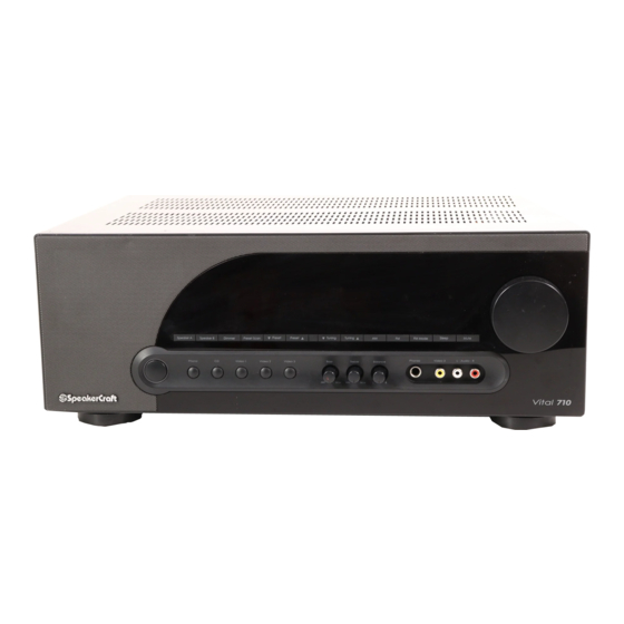
- Page 1 INSTALLATION INSTRUCTIONS Vital 710 80W x 2 Channel A/V Receiver...
-
Page 2: Safety Instructions
SAFETY INSTRUCTIONS APPLICABLE FOR USA, CANADA OR WHERE APPROVED FOR USAGE CAUTION: To reduce the risk of elec- CAUTION: TO PREVENT ELECTRIC tric shock, do not remove cover (or back). No user-serviceable parts SHOCK, MATCH WIDE BLADE PLUG TO inside. Refer servicing to qualified ser- WIDE SLOT, INSERT FULLY. -
Page 3: Table Of Contents
FRONT PANEL CONNECTIONS ..........................24 Video 3 Front Panel Connections ........................24 Headphones Connection ............................ 24 OPERATING THE Vital 710 ............................25 Install Vital 710 Remote Batteries ..........................25 Turning ON the Vital 710 ............................25 Selecting Speakers A/B ............................25 Volume ..................................26 Mute ................................... -
Page 4: Introduction
The Vital 710 also features a Front Panel Headphone Jack for private listening plus, a Sleep Timer has been built in to the Vital 710, to automatically shut the Vital 710 OFF for those late night sessions when the Vital 710 could keep running long after you have drifted off to sleep. -
Page 5: What's Included
Vital 710 FEATURES WHAT’S INCLUDED 1 - Vital 710 Stereo A/V Receiver 1 - Vital 710 IR Remote Control 2 - AAA Batteries 1 - FM Indoor Antenna SP. A 1 - AM Loop Antenna 1 - Front Panel Jack Cover... -
Page 6: Front Panel
FRONT PANEL 1. ON/STANDBY - Press this button to turn the Vital 710 ON/OFF. In Standby, the backlight will be OFF. To turn the unit ON, press the button. The backlight illuminates white and the Front Panel Display turns ON. The Vital 710 will go through a power up sequence of about five seconds after which the receiver is ready for use. - Page 7 14. Am and Fm - In Standby or with the Vital 710 power ON, press this button to turn the Vital 710 ON, (if OFF) and select the AM Tuner. The tuner will select the last tuned AM Channel.
- Page 8 Pre-Out Jacks. 18. VOLUmE - With the Vital 710 ON turn this knob to adjust the speaker level audio output. Turn clockwise (right) to turn volume up; turn counterclockwise (left) to turn the volume down. The audio output level in dB (deci- bels) will be displayed on the Front Panel Display while the knob is being turned and for five seconds after a volume adjustment is made.
-
Page 9: Rear Panel
22. CD IN - (2 RCA Jacks) Connect to the left and right line level audio outputs of a CD Player or other device such as a MP3 Player, Music Server, etc. CD IN is selected by pressing the CD button on either the Vital 710 Front Panel or Remote Control. - Page 10 VID 1 Out Jacks output line level audio and composite video from the currently selected source. (If it is an A/V source.) VID 1 In is selected by pressing the Video 1 button on the Vital 710 Front Panel or Remote Con- trol.
- Page 11 Main In can be connected to the external amp loop out to utilize the Vital 710 amplifier as an ad- ditional room in the system. 35. SPEAKER A - Connect the Left + and Left - Speaker A five way binding posts on the Vital 710 to the main room Left + and Left - Speaker Terminals.
-
Page 12: Vital 710 Remote Features
46. AUTO PRESET - With the FM Band selected, press this button automatically program the Preset Channels with the first 30 tunable FM channels found. The Vital 710 can store up to 30 Presets. If fewer than 30 FM channels are found the Vital 710 will cycle the FM Band a second time to try to find more channels. - Page 13 B. When selected the Front Panel Display will indicate ‘SP.B’ to show Speaker B is active. 58. Am - In Standby or with the Vital 710 power ON, press this button to turn the Vital 710 ON, (if OFF) and select the AM Band.
-
Page 14: Installation
2. Never remove the feet on the bottom of the Vital 710. 3. Leave at least 2 inches above and 1 inch on each side of the Vital 710 for free air flow. 4. Whenever possible, provide vent holes in the shelf under the Vital 710 to increase air flow into the bottom of the unit. -
Page 15: Speaker Placement
Ceiling speakers are very popular in modern architecture. Ceiling speakers, like bookshelf or inwall speakers, should be placed at an equal distance from each other and the Primary Listening Area. Many SpeakerCraft ceiling speakers have pivoting tweeters that can ‘focus’ the high frequency content directly to the Primary Listening Area and compensate for sometimes less than desirable placement so the sound will still be bal- anced with the Video Display. -
Page 16: Connections
Note: Do not connect more than one pair of 4Ω speakers directly to the Vital 710. Do not connect more than one pair of 8Ω speakers directly to the Speaker A and B Terminals at the same time. This will cause the Vital 710 to shut down and can damage the unit. -
Page 17: Subwoofer
Note: Do not connect more than one pair of 4Ω speakers directly to the Vital 710. Do not connect more than one pair of 8Ω speakers directly to the Speaker A and B Terminals at the same time. This will cause the Vital 710 to shut down and can damage the unit. -
Page 18: Multiple Pair Speaker Hookup For A Multiroom Sound System
4Ω speakers directly to the Vital 710. Multiple 4Ω speaker pair connected directly to the Vital 710 will cause the Vital 710 to shut down and can damage the Vital 710. This type of damage is not covered by the Warranty. - Page 19 All four pair should be connected to the Speaker A Terminal as shown in Figure 8. Setting Impedance The Vital 710 is capable of handling a 4Ω load. For 4Ω amp configuration using SpeakerCraft VSi60 Impedance Matching Volume Controls, use Chart 1. If using another impedance matching device follow the manufacturer’s instructions for that device.
- Page 20 Correct connections as necessary. 12. For regular use, set the room volume controls to full ON. Adjust the Vital 710 to a good listening level. Leave the Vital 710 volume control in that setting and adjust volume with the individual room volume controls.
-
Page 21: Rear Panel Connections
Connect a CD Player to CD IN as shown in Figure 11. 1. Using a stereo RCA-RCA patch cable with gold Figure 11 CD Connections ends, connect the L & R line level audio outputs of a CD Player to L & R CD IN on the Vital 710 Rear Panel. -
Page 22: Tape In/Out Connections
1. Using a stereo A/V patch cable with gold ends, connect the L&R line level audio OUT of the DVD Vital 710 VID 2 Audio IN Player to the L & R VID 2 Audio IN on the Vital 710. Stereo Audio/Video Patch Cable Connect the composite video OUT of DVD Player to the VID 2 Video IN on the Vital 710. -
Page 23: Video 3 Rear Panel Connections
3. If using source components that feature IR Control Inputs, using a mono mini-mini cable connect the Re- mote OUT on the Vital 710 Rear Panel to the IR Remote IN Jack on the device being controlled. 4. To connect additional devices with IR Remote Inputs, connect a mono mini-mini cable to the IR Remote... -
Page 24: Ac Outlets Connections
Vital 710 Front Panel connect the L & R line level audio OUT of the Cable Box to L & R VID 3 Audio IN on the Vital 710. Con- nect the composite video OUT on the Cable Box to the VID 3 Video IN on the Vital 710. -
Page 25: Operating The Vital 710
OPERATING THE Vital 710 OPERATING THE Vital 710 Before operating the Vital 710, be sure all instructions from the previous sections have been followed regarding installation and connections. Install Vital 710 Remote Batteries Vital 710 Remote Rear The Vital 710 Remote Control comes with two AAA batteries. -
Page 26: Volume
Vital 710 Front Panel Tone and Balance Controls Bass Turn the Bass Knob on the Vital 710 Front Panel to adjust the bass (low frequencies) in the speaker level output. Turn counterclockwise (left) to reduce bass; turn clockwise (right) to increase bass. Center de- tente (click) is flat bass EQ. -
Page 27: Selecting A Source
Front Panel Display as shown Vital 710 Front Panel Vital 710 Remote in Figure 27. If the Vital 710 is in Standby a press of one of these buttons will turn the Vital 710 ON and select the source. -
Page 28: Presets
Presets The Vital 710 can store up to 30 AM or FM Preset Channels (30 total). They can be stored manually by individu- ally tuning channels and saving them as Presets. The Auto Preset function can be used to quickly store up to 30 FM channels. -
Page 29: Dimmer
OPERATING THE Vital 710 Dimmer Press the Dimmer button on the Vital 710 front Panel or Vital 710 Remote to control of the brightness of the SP. A B Front Panel Display. When the Vital 710 is turned ON, the Front Panel Display will illuminate to full brightness. -
Page 30: Tape Monitor (Audio Recording)
In unusual circumstances, it may be necessary to reset the Vital 710 microprocessor. After a power outage or surge, the Vital 710 may not fully restore to normal operation. It may also be used to reset the Vital 710 to fac- tory defaults. -
Page 31: Troubleshooting
Unit does not power up. a) Confirm Power Cord is plugged in to an unswitched 110V AC Outlet. ON/Standby button Backlight does not illuminate b) Confirm Main Power Switch on Vital 710 Rear Panel is in the ON position. Audio No Sound From Speakers a) Confirm source audio connections. -
Page 32: Specifications
SPECIFICATIONS Audio Sections Power Output/Channel (RMS, two channels driven into 8 Ohms) 80 Watts, 20Hz to 20kHz THD (at rated power) <0.007% Power/Channel (RMS, 2 channels driven into 4 Ohms) 125 Watts <0.1% @ 1kHz Damping Factor > 100 Input Sensitivity (For rated power @ max VC) 220 mV Line IN, 2.0mV Phono IN Input Impedance (Source Inputs) 11 K Ohms Line IN, >20 k Ohms Phono IN... - Page 33 SPECIFICATIONS Control Sections Trigger Outputs (0 to 15 V DC) 14 V @ 10 mA, 9.0V @100mA General Power Consumption 120V Version Standby <1 Watt No signal (idle) 55 Watts At 1/8 Rated Power (10 Watts/Channel, 8Ω) 180 Watts At 1/8 of 125 Watts (15.6 Watts/Channel, 4Ω) 260 Watts Rear Panel marked Line Ratings 120 VAC, 60 Hz, 230 Watts...
-
Page 34: Limited 2-Year Warranty
SpeakerCraft be liable for any incidental or consequential damages arising out of the use or inability to use the product, even if SpeakerCraft has been advised of the possibility of such damages, or for any claim by any other party. Notwithstanding the above, if you qualify as a “consumer” under the Magnuson-Moss Warranty Act, then you may be entitled to any implied warranties allowed by law for the Warranty Period. - Page 35 NOTES...
- Page 36 940 Columbia Avenue, Riverside, CA 92507 (800) 448-0976 Fax (951) 787-8747 www.speakercraft.com © 2009 SpeakerCraft, Inc. LITRCV710 REV.1...
Need help?
Do you have a question about the Vital 710 and is the answer not in the manual?
Questions and answers