Table of Contents
Advertisement
Quick Links
Advertisement
Table of Contents

Related Manuals for Telex USR-100

Summary of Contents for Telex USR-100
- Page 1 Telex Operating Instructions USR-100...
-
Page 2: Table Of Contents
General ..........1 USR-100 Features ........1 Frequency Agility . - Page 3 Table of Contents (continued) SH-100 Features ........11 Power Switch .
-
Page 4: General
A 2 digit 7 Segment LED indicates the Channel. If there is any interference from other wireless users or a TV station in the area, it is a simple matter to change the USR-100 frequency. The frequency agility of the USR-100 is also very useful for itinerant users and rental customers. -
Page 5: Posi Phase Diversity
Posi Phase Diversity The USR-100 receiver utilizes Telex’s patented Posi Phase auto diversity circuit. Unlike other types of diversity which receive with only one antenna at a time, Posi Phase utilizes both antennas at all times. This results in a stronger signal from the microphone for cleaner audio and greater range. -
Page 6: Displays
Power The USR-100 will operate from the supplied AC adapter or any nominal 12-15 volt AC/DC 600 mA supply. Audio The USR-100 audio circuitry is designed to complement the trans- mitter audio. -
Page 7: Usr-100
USR-100 Receiver Specifications RF Frequency Range....668.0 to 746.0 MHz Channels ..100 (0-99) (within TV Ch. 47/48 & 58/59) R.F. Stability ......0.005% or better Modulation Type . -
Page 8: Sh-100
Model SH-100 Transmitter Specifications Frequency of operation ..668.000 to 746.000 MHz. (Current models operate in 2 frequency ranges.) 668.000 to 679.500 MHz and 734.100 to 745.500 MHz. Number of Channels ..100 User Selectable Channels in each range. -
Page 9: Lt-100
Model LT-100 Transmitter Specifications Frequency of operation ..668.000 to 746.000 MHz. (Current models operate in 2 frequency ranges.) 668.000 to 679.500 MHz and 734.100 to 745.500 MHz. Number of Channels ....100 User Selectable Channels in each range. -
Page 10: Power Switch
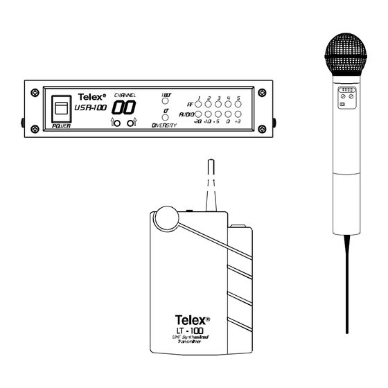
Figure 1 Front Panel Power Switch: When turned on, the channel display illuminates and one of the diversity lights will come on. Channel Select Buttons: Push once to increase display by one. Push and hold to increase display more than one. Left button changes “10’s”, Right button changes “1’s”. -
Page 11: Antenna Jacks
Figure 2 Rear Panel Antenna Jacks: Two antenna jacks for posi phase diversity recep- tion. Attach an antenna to each jack. Audio Output: XLR type jack connects to audio sound system (Amplifier/Mixer). Pin 1 ground, Pin 2 +, Pin 3 -. Audio Adjust: Screwdriver adjustable potentiometer, controls audio output. -
Page 12: Receiver Set-Up
Insert the other end of the audio cable into the input of your Mixer/Amplifier. Set the Audio Level Switch on the USR-100 to match the input level of your audio system. If utilizing the two 1/4 wave antennas supplied, connect both of them to the back of the receiver at a 90 angle as shown in Figure 3. - Page 13 Bottom View Figure 4 SH-100 -10-...
-
Page 14: Sh-100 Features
SH-100 Power Switch: Located on the bottom of the handle. Battery Test Button: Press to check the remaining life of the batteries. Battery Meter: The number of segments that light when the Battery Test Button is pushed indicate the approximate time of battery life remaining. -
Page 15: Power Switch
Top View Back View Side View Figure 5 LT-100 LT-100 Power Switch: Located on the top of the case. Battery Test Button: Press to check the remaining life of the batteries. Battery Meter: The number of segments that light when the Battery Test Button is pushed indicate the approximate time of battery life remaining. -
Page 16: Channel Select Switches
Battery Meter Number of Lights Time Remaining Time Remaining High Power Low Power (alkaline batteries, (alkaline batteries, intermittent usage) intermittent usage) 3 grn 1 red 9 hours or less 12 hours or less 2 grn 1 red 7 1/2 hours or less 9 hours or less 1 grn 1 red 6 hours or less... -
Page 17: System Set-Up
Antenna Placement The antennas and USR-100 should be placed in a location with a clear “signal path” to the transmitter. This “path” should be as short and free of obstructions as possible. Obstructions, such as walls, ceilings, and metal objects, will reduce range and performance. -
Page 18: Bracket Mounting
Remote mounting antennas will increase the effective reception range when appropriately positioned. The two 1/4 wave antennas supplied are not ground independent and therefore not appropriate for remote mounting. See the accessories section of this manual for remote- mountable antenna options. The diversity antenna system operates most efficiently when the two antennas are separated as much as possible The antennas should be mounted so that they are at least 6 feet (2... -
Page 19: Antenna Connection
If possible, do not mount the brackets on a wall. See Figure 7 for bracket and antenna placement. Antenna Connection Attach the two antenna cables to the back of the USR-100. Be sure the connectors are tightened securely. Route the cable to the antennas and attach in the same manner. -
Page 20: Installing Rack Mounts
Installing Rack Mounts The USR-100 is supplied with rack mounts for both double and single mounting in a 19" equipment rack. For single mounting, the long and short rack “ears” are used. For dual mounting, use the short “ears and the mid brackets from two USR-100’s. -
Page 21: Double Mounting
Double Mounting: Align the mid brackets (Item No. 2) with the holes on the adjacent sides of each unit. Install the previously removed screws. Insert an additional screw (Item No. 4 provided in the parts pack) into the remaining holes. Tighten all screws securely. -
Page 22: Accessories And Replacement
ACCESSORIES AND REPLACEMENT PARTS Model CLA-X - 1/2 Wave Antenna - for remote mounting Model Part No. Band Color Frequency CLA-1 870658-1 Blue 520-564.9 MHz CLA-2 870658-2 Yellow 565-614.9 MHz CLA-3 870658-3 615-659.9 MHz CLA-4 870658-4 White 660-689.9 MHz CLA-5 870658-5 Green 690-724.9 MHz... -
Page 23: Front Connector Mounting Kit
Order No. 71147000 Model UAD-2 Four Way Antenna Splitter Order No. 71253000 Feeds four USR-100’s with just two antennas. Also supplies power. Eliminates 3-power supplies and 6 antennas Front Connector Mounting Kit Part No. 878978 This kit consists of 4 cable and connector assemblies with “TNC” type connectors. -
Page 24: Fcc Information
FCC INFORMATION The TELEX Model USR-100 receiver is authorized under Part 15 of the Federal Communication Commission. Licensing of TELEX equip- ment is the user’s responsibility and licensability depends upon the user’s classification, and frequency selected. TELEX strongly urges the user to contact the appropriate telecommunications authority before ordering and choosing frequencies other than factory preset frequencies. -
Page 25: Customer Service Information
Damage claims must be settled between you and the carrier and this can delay repair and return of the unit to you. Telex reserves the right to make changes in design and improvement on its product without assuming any obligation to install the same on any of its products previously manufactured. - Page 26 TELEX COMMUNICATIONS, INC. 8601 East Cor nhusker Highway w P.O. Box 5579 w Lincoln, Nebraska 68505-5579 PN 801585-1 JUNE 1998...
Need help?
Do you have a question about the USR-100 and is the answer not in the manual?
Questions and answers