
Subscribe to Our Youtube Channel
Related Manuals for All-sun TRUE RMS


Summary of Contents for All-sun TRUE RMS
- Page 1 TRUE RMS DIGITAL MULTIMETER OWNERS MANUAL http://www.all-sun.com Read this owners manual thoroughly before use 6000...
-
Page 2: Warranty
GENERAL DESCRIPTION This multimeter is compact 3 5/6-digit true rms digital multimeter with the USB2.0 standard interface. It can be used for measuring DC voltage, DC current, true-rms AC... - Page 3 FEATURES 1. Measures the true-rms values of ac voltage and ac current. 2. Transfers the measurement readings of the meter to a computer through standard USB port. 3. Provides analog bar graph, reading unit indication and backlight. 4. The sampling rate is 3 times/sec. The bar graph updates at 30 times/sec.
-
Page 4: Safety Information
SAFETY INFORMATION This meter has been designed according to IEC-61010 concerning electronic measuring instruments with a mea- surement category (CAT III 600 V) and pollution degree 2. Warning To avoid possible electric shock or personal injury, follow these guidelines: Do not use the meter if it is damaged. Before you use the meter, inspect the case. - Page 5 connecting the meter in the circuit. Remember to place the meter in series with the circuit. When servicing the meter, use only specified replacement parts. Use caution when working above 30Vac rms, 42V peak, or 60Vdc. Such voltages pose a shock hazard. When using the probes, keep your fingers behind the finger guards on the probes.
- Page 6 Do not use the meter in a manner not specified by this manual or the safety features of the meter may be impaired. Remaining endangerment: When an input terminal is connected to dangerous live potential it is to be noted that this potential at all other terminals can occur! CATII - Measurement Category II is for measurements performed on circuits directly connected to low voltage...
- Page 7 Caution To avoid possible damage to the meter or to the equipment under test, follow these guidelines: Disconnect circuit power and discharge all capacitors before testing resistance, diode, capacitor, temperature and continuity. Use the proper terminals, function, and range for your measurements.
- Page 8 SYMBOLS AC (Alternating Current) DC (Direct Current) DC or AC (alternating current or direct current) Important safety information. Refer to the manual. Dangerous voltage may be present. Be cautious. Earth ground Fuse Conforms to European Union directives Double insulated Low battery Diode...
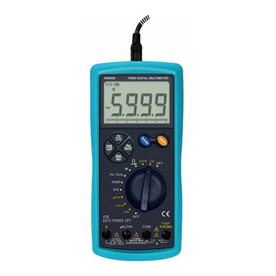
- Page 9 INSTRUCTION Meter Instruction Figure 1...
- Page 10 1. Display LCD display, with a max. reading of 9999 2. " " button Press this button to set the meter to Relative Mode, and " " will appear as an indicator. To exit Relative Mode, press this button again, and " " will disappear. Pressing and holding down this button for about 2 seconds set the meter to USB communication mode (In this mode, you can transfer the readings of the meter...
- Page 11 button again to exit Data Hold mode, and " " will disappear. Press and hold down this button for about 2 seconds to enable or disable the backlight. The backlight will turn off automatically about 10 seconds later after it is turned 5.
- Page 12 8. " A /mA" jack Plug-in connector for the red test lead for current *< 600mA *measurements. 9. "COM" Jack Plug-in connector for the black test lead for all measurements. 10. " V*Hz" jack Plug-in connector for the red test lead for all measurements except current measurements.
-
Page 13: Lcd Display
How to Connect the Adapter Capacitance test socket Transistor test socket Figure 2 LCD Display 6 5 4 3 1 Figure 3... - Page 14 ----- Duty Cycle is selected -----Fahrenheit temperature test is selected -----Celsius degree test is selected --- Transistor hFE test is selected ---- Continuity test is selected --- Diode test is selected ---- Relative mode is active --- USB serial port communication is enabled ---- Data Hold is enabled ---Autorange mode is selected --- Automatic power-off mode is selected...
-
Page 15: Using The Bar Graph
Using the Bar Graph The bar graph at the bottom part of the LCD is a analog display only for the measurements of ac/dc voltage, ac/dc current and resistance. The length of its lit segments is proportional to the present reading on the LCD. The bar graph is unavailable for the other measurements. - Page 16 Units on the LCD Voltage unit mV*V mV: Millivolt ; V: Volt; 1V=10 Current unit µ A*mA* µ A: Microamp; mA: Milliamp; A: Ampere; 1A=10 mA=10 µ A Resistance unit : Ohm; k : Kilohm; M : Megohm; 1M =10 k =10 Capacitance unit nF* µ...
-
Page 17: General Specification
GENERAL SPECIFICATION Maximum Voltage between any Terminal and Earth Ground: 600Vrms Fuse Protection for "µAmA" Jack Inputs: 500mA, 1000V, FAST, Min. Interrupt Rating 20000A Fuse Protection for "A" Jack Inputs: 20A, 1000V, FAST, Min. Interrupt Rating 20000A Display: LCD, with a max. reading 9999 Overrange Indication: "OL"... - Page 18 Input Impedance: 60mV and 600mV ranges: >100M* the other ranges: 10M* Overload Protection: AC600V; Crest Factor: 3.0 Reading: True rms Frequency: 40Hz~400Hz Note: When the input terminals are shorted, the display may show a reading. It doesn't matter and will not...
- Page 19 DC Current Range Resolution Accuracy Remark 600.0µA 0.1µA autorange 6000µA 1.0µA ±(1.0%+7) 60.00mA 0.01mA autorange 600.0mA 0.1mA 6.000A autorange ±(1.5%+7) 10mA Overload Protection: For "µA/mA" jack inputs: Fuse, 500mA/1000V, fast action, For "A" jack inputs: Fuse, 20A/1000V, fast action, Max. Input Current: 20A ( For inputs > 5A : measurement duration<10 secs, interval >15 minutes ) AC Current Range...
- Page 20 Frequency: 40Hz~400Hz Crest Factor: 3.0 Reading: True rms Note: When the input terminals are shorted, the display may show a reading. It doesn't matter and will not affect the measurement accuracy. Resistance Range Resolution Accuracy 600.0 ±(1.0%+5) 6.000k 60.00k ±(0.8%+5) 600.0k...
-
Page 21: Transistor Hfe
Frequency Range Resolution Accuracy 9.999Hz 0.001Hz 99.99Hz 0.01Hz 999.9Hz 0.1Hz 9.999kHz ±(1.0%+5) 99.99kHz 10Hz 999.9kHz 100Hz 9.999MHz 1kHz Not specified Input Voltage: 0.5 ~ 3Vpp Overload Protection: AC600V Note : Frequency measurements are autoranging. Transistor hFE Range Resolution Test Condition Vce 2.2V*I Overload Protection: AC600V... - Page 22 Capacitance ( use Relative mode) Range Resolution Accuracy 40.00nF 10pF ±(3.5%+5) 100pF 400.0nF ±(2.5%+5) 4.000µF ±(3.5%+5) 40.00µF 10nF ±(4.0%+5) 400.0µF 100nF ±(5.0%+5) 4000µF 1µF not specified Overload Protection: AC600V Temperature Range Scope Resolution Accuracy -20°C ~ 0°C 0.1°C ±(6.0%+5°C) 0°C ~ 400°C 0.1°C ±(1.5%+4°C) °C...
-
Page 23: Duty Cycle
Duty Cycle Scope Resolution Accuracy 5% ~ 95% 0.1% *(2%+7) The Duty range is an autorange. Input Voltage: 4 ~ 10Vp-p; Frequency Range: 1Hz~5kHz Overload Protection: AC600V Diode Range Resolution Test Current Open Circuit Voltage about 0.8mA about 3V Overload Protection: AC600V Continuity Range Introduction... -
Page 24: Operation Introduction
OPERATION INTRODUCTION Using Relative Mode Relative mode is available in some functions. Selecting relative mode causes the meter to store the present reading as a reference for subsequent measurements. 1. Press the " " button, the meter enters the relative mode and store the present reading as a reference for subsequent measurements, and "... -
Page 25: Measuring Voltage
Measuring Voltage 1. Connect the black test lead to the "COM" jack and the red test lead to the " V Hz" jack. 2. Set the range switch to the desired V or mV range. If the magnitude of the voltage to be measured is not known beforehand, select the highest range and then reduce it range by range until satisfactory resolution is obtained. -
Page 26: Measuring Current
Measuring Current 1. Set the range switch to desired µA , mA or A range. If the magnitude of the current to be measured is not known beforehand, select the highest range and then reduce it range by range until satisfactory resolution is obtained. -
Page 27: Measuring Resistance
Note: For frequency measurement, the display will show zero or other indefinite values if the voltage of the input signal is less than about 300mV rms. It is normal. Note: When the range switch is in the "A " range position, you must use the "A"... -
Page 28: Continuity Test
3. Before measuring in-circuit resistance, make sure that the circuit under test has all power removed and all capacitors are fully discharged. Continuity Test 1. Connect the black test lead to the "COM" jack and the red test lead to the " V Hz"... -
Page 29: Measuring Capacitance
Measuring Capacitance 1. Set the range switch to " " position. 2. Refer to the Figure 2, connect the adapter to the "COM" jack and the " V Hz" jack. Don't reverse the connection. 3. Press the " " button, the meter enters the Relative mode and "... -
Page 30: Measuring Frequency
Measuring Frequency 1. Connect the black test lead to the "COM" jack and the red test lead to the " V Hz" jack (Note:The polarity of the red lead is positive " " ) . 2. Set the range switch to Hz/DUTY position, the display shows "Hz". -
Page 31: Measuring Duty Cycle
Measuring Duty Cycle 1. Connect the black test lead to the "COM" jack and the red test lead to the " V Hz" jack. 2. Set the range switch to Hz/DUTY position. 3. Press the " " button to select duty cycle measurement, the display shows "%". - Page 32 4. Connect the red test lead to the anode of the diode to be tested, and the black test lead to the cathode. 5. The display will show the approximate forward voltage of the diode. If the connection is reversed, "OL" will be shown on the display.
-
Page 33: Measuring Temperature
Measuring temperature 1. Set the range switch to "TEMP" position, the display will show the compensation temperature which is similar to the environment temperature. 2. Connect the negative " " plug of the k type thermocouple to the "COM" jack, and the positive " "... -
Page 34: Auto Power Off
Auto Power Off The display blanks and the meter goes into "Sleep" mode if you do not turn the rotary switch or press any button for about 15 minutes. While in Sleep mode, pressing any button or turning the rotary switch turns on the meter. -
Page 35: General Maintenance
MAINTENANCE Warning Except replacing fuses and battery, never attempt to repair or service the meter unless you are qualified to do so and have the relevant calibration, performance test, and service instructions. The meter should be stored in dry place. Don't store it in intensive electromagnetic field environment. -
Page 36: Replacing The Battery And Fuse
Replacing the Battery and Fuse Warning To avoid false readings, which could lead to possible electric shock or personal injury, replace the battery as ") appears. soon as the battery indicator (" To prevent damage or injury, install only replacement fuses with the specified amperage, voltage, and interrupt ratings. - Page 37 To open the battery cover screw-type lock Figure 4 This meter uses two fuses: Fuse1 : 500mA, 1000V, FAST, Min. Interrupt Rating 20000A, Ø10X38mm Fuse 2 : 20A, 1000V, FAST, Min. Interrupt Rating 20000A, Ø10X38mm To replace the fuse, remove the meter from its holster, remove the screws on the back cover, remove the back cover, replace the fuse with a new one of the same ratings.
- Page 38 1 piece CD ( containing USB driver and the communication application ) : 1 piece http://www.all-sun.com DISPOSAL OF THIS ARTICLE Dear Customer, If you at some point intend to dispose of this article, then please keep in mind that many of its components consist of valuable materials, which can be recycled.
- Page 39 DATA TRANSMITTION PROGRAM operation instruction SYSTEM REQUIREMENT To run this application, there are some requirements for the system as follows: Operating system : Microsoft Windows 98SE/2000/XP/2003/VISTA Memory: 128MB RAM or more Monitor: SuperVGA monitor (or better), with the resolution of 800 x 600 or higher Harddisk space: 10MB (or more) free space CD-ROM drive USB port...
- Page 40 BUTTON BAR INSTRUCTION: Figure 2 1 State : Indicate the status of the present data transmission. 2 New : Click to establish a new database. 3 Open : Open the databases with the extension of ".db". 4 Save as : Save the present file as another file in one of the 6 formats. The extensions for the 6 formats are: ".db", ".xls", ".txt", ".csv", ".htm", and ".rtf".
- Page 41 The Data Grid area is for setting for the data in the data recording area. Enable Alarm check box : Enable or disable the color-data alarm feature when the recorded readings are beyond the upper or lower limit which will be specified later.
Need help?
Do you have a question about the TRUE RMS and is the answer not in the manual?
Questions and answers