Table of Contents
Advertisement
Installation, Operation,
and Maintenance
Gas Unit Heater
Separated Combustion Indoor Gas-Fired Duct Furnace
Only qualified personnel should install and service the equipment. The installation, starting up, and
servicing of heating, ventilating, and air-conditioning equipment can be hazardous and requires specific
knowledge and training. Improperly installed, adjusted or altered equipment by an unqualified person could
result in death or serious injury. When working on the equipment, observe all precautions in the literature
and on the tags, stickers, and labels that are attached to the equipment.
March 2012
SAFETY WARNING
GMND-SVX01B-EN
Advertisement
Table of Contents

Subscribe to Our Youtube Channel
Related Manuals for Trane GMND-SVX01B-EN


Summary of Contents for Trane GMND-SVX01B-EN
- Page 1 Improperly installed, adjusted or altered equipment by an unqualified person could result in death or serious injury. When working on the equipment, observe all precautions in the literature and on the tags, stickers, and labels that are attached to the equipment. GMND-SVX01B-EN March 2012...
-
Page 2: Warnings, Cautions And Notices
ATTENTION: READ THIS MANUAL AND ALL LABELS compounds have the same potential impact to the ATTACHED TO THE UNIT CAREFULLY BEFORE environment. Trane advocates the responsible handling of ATTEMPTING TO INSTALL, OPERATE OR SERVICE THESE all refrigerants-including industry replacements for CFCs UNITS! CHECK UNIT DATA PLATE FOR TYPE OF GAS AND such as HCFCs and HFCs. - Page 3 Improper installation, Trane and the Trane logo are trademarks of Trane in the adjustment, alteration, service or use of this product United States and other countries. All trademarks could cause flammable mixtures.
- Page 4 Important: It is the equipment owner’s responsibility to provide any scaffolding or other apparatus required to perform emergency service or annual/periodic maintenance to this equipment. GMND-SVX01B-EN...
-
Page 5: Table Of Contents
......35 Troubleshooting ..... . 35 GMND-SVX01B-EN... -
Page 6: Model Number Descriptions
External 0–10 Vdc Input Single Stage Direct Spark Ignition = Two-Stage, Direct Spark Ignition Digit 10 — Design Sequence Seventh Design Digit 11 — Heat Exchanger Material Aluminized Steel #321 Stainless Steel Digit 12 — Rooftop Arrangements None (Indoor Unit) GMND-SVX01B-EN... -
Page 7: General Information
This should be accomplished by conform with local building codes, or in absence connecting a grounded conductor between the of local building codes, with CGA-B149.1 service panel and the furnace. To ensure a proper “Installation Codes for Natural Gas Burning GMND-SVX01B-EN... -
Page 8: Identification Of Parts
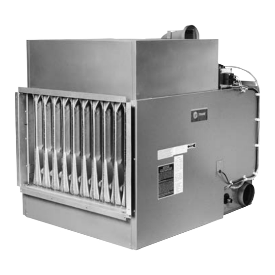
1 psig = 6.894 kPa 1 liter/second = CFM x 0.472 1 pound = 0.453 kg 1000 Btu per hour = 0.293 kW 1 gallon = 3.785 L 1000 Btu/Cu. Ft. = 37.5 MJ/m 1 cubic foot = 0.028 m GMND-SVX01B-EN... - Page 9 General Information Figure 2. Internal furnace assembly Flue Collector Heat Exchanger Burner Drawer GMND-SVX01B-EN...
-
Page 10: Unit Dimensions And Weights
40-1/4 41-7/8 1/2 or 3/4 (1083) (1022) (1064) (152) (156) 48-1/8 45-3/4 47-3/8 1/2 or 3/4 (1222) (1162) (1203) (152) (174) (a) “D” dia. equals the air inlet opening and the flue discharge opening. Figure 3. Dimensions, standard units GMND-SVX01B-EN... - Page 11 At altitudes of 2,000 to 4,500 feet (610 to 1,372 m), the units must be orificed to 90 percent of the normal altitude rating, and be so marked in accordance with the ETL certification. Figure 4. Temperature rise and pressure drop graph GMND-SVX01B-EN...
-
Page 12: Installation: Mechanical
6” (152 mm) setting cannot be maintained. Failure to follow these Note: When the clearances required for accessibility are greater than the recommendations could result in equipment or minimum required safety clearances, the accessibility clearances property damage. take precedence. GMND-SVX01B-EN... -
Page 13: Air Flow
If this cfm delivery is greater than that required for heating, resulting in a low air temperature rise, install a damper GMND-SVX01B-EN... -
Page 14: Suspension
(P/N 251-07944 and 251-07946) to the unit heater using the holes to which the louvers were attached. 5. Using the enclosed #8-18 x 1/2 screws and with the top panel oriented such that the side with the larger holes GMND-SVX01B-EN... - Page 15 (P/N 251-07945) and to the right side panel (P/N 251-07947). Note: The top and bottom panels must be attached so that the sides with the larger holes are facing the unit heater; this makes the assembly easier. 10. Install the louvers and cone springs. GMND-SVX01B-EN...
-
Page 16: Installation: Piping
Failure to follow these instructions could result in death or serious injury. Before any connection is made to an existing line supplying other gas appliances, contact the local gas company to make certain that the existing line is of adequate size to handle the combined load. GMND-SVX01B-EN... -
Page 17: Pipe Installation
If gas pressure is excessive on natural gas applications, install a pressure regulating valve in the line upstream a. Manual “A” valve from the main shutoff valve. b. Manual “B” valve c. Solenoid valve d. Pilot safety e. Pressure regulator GMND-SVX01B-EN... -
Page 18: Installation: Venting
D 3 6 31 C The appliance and its individual shutoff valve must be disconnected from the gas supply piping system during any pressure testing of that system in excess of 1/2 psig (3.5 kPa). GMND-SVX01B-EN... -
Page 19: Exhaust Venting
Equipment” or CAN/CGA-B149.2, “Installation Codes corrosion resistant screws. Two full turns of 3M™ #425 for Propane Gas Burning Appliances and Equipment” . Aluminum Foil Tape or its equivalent must then be used to seal each joint. General Electric RTV-108, Dow GMND-SVX01B-EN... - Page 20 (1 m) from any building opening, and more than four feet (1.3 m) from, and not directly above, any electric meter, regulator, or relief equipment (refer to Figure 10, p. 21 Figure 12, p. 21). GMND-SVX01B-EN...
-
Page 21: Installation: Concentric Vent Terminal
In most applications, the terminal should be on level with the flue outlet of the unit, less 1/4 inch per foot pitch for condensate drainage toward the outside of the building (see Figure 13, p. 22). Figure 11. Horizontal intake/vent locations GMND-SVX01B-EN... -
Page 22: Vertical Termination
Add an additional 5- inch pipe, if necessary, so that the base of the exhaust cap will be 16 to 24 inches from the combustion air inlet (see Figure 14, p. 22, Step 2). GMND-SVX01B-EN... - Page 23 Seal the joint between the 5-inch 6 inches of combustible material. pipe and the inlet air cap with silicone sealant to prevent the entry of water (see Figure 16, p. 23, Step 4). GMND-SVX01B-EN...
-
Page 24: Installation: Electrical
NFPA No. 70 National Electrical Code and applicable local codes; in Canada, to the Canadian Electrical Code, Part 1 CSA Standard C22.1. Thermostat Heat Anticipator Adjustments. initial heat anticipator setpoint should equal the thermostat’s current amperage draw when the unit is GMND-SVX01B-EN... - Page 25 105°C. Should any high limit wires have to be replaced, they must be replaced with wiring material having a temperature rating of 200°C minimum. GMND-SVX01B-EN...
-
Page 26: Start-Up
Shut-Down 1. Turn the valve selector knob to the OFF position. 2. Turn off the electricity. 3. To relight, follow the instructions in “Initial Lighting, ” p. 26 (preceding section). GMND-SVX01B-EN... - Page 27 8A. Main Gas Valve (Honeywell) 8B. Main Gas Valve (White-Rodgers) 9. Honeywell Ignitor 10. Honeywell Pilot Burner 11. Honeywell Pilot Orifice 12. Honeywell Electrode/Sensor Lead 13. Hi Limit Switch (Located on Rear Header Plate of Heat Exchanger, Air Inlet Side) GMND-SVX01B-EN...
- Page 28 If the unit is equipped with a pressure regulator on the combination gas valve, follow Step a through Step d (above). If the unit is not so equipped, the propane gas supply system GMND-SVX01B-EN...
-
Page 29: Pilot Adjustment
The adjusted manifold pressure should not vary more than 10 percent from the pressures specified in Table 7, p. GMND-SVX01B-EN... -
Page 30: Gas Equipment Start-Up
External static pressure _________ in. wc Check rotation of main . Check motor amps L1 _____ L2 _____ L3 _____ Blower RPM _____________ Check air filters. (Record quantity & size.) Remarks: _____________________________________________________________________________________________________ _______________________________________________________________________________________________________________ _______________________________________________________________________________________________________________ GMND-SVX01B-EN... -
Page 31: Maintenance
Check and test the operational functions of all safety tapping. Turn the manual valve on to apply pressure to the devices supplied with your unit. combination control. Note the pressure reading on the GMND-SVX01B-EN... - Page 32 3. Flue Sizes: 100/175 units: 4” dia. flue outlet Reducer required—to be supplied by installer. 200/250 units: 5” dia. flue outlet (no adapter required). 300/400 units: 6” dia. flue outlet Increaser required—to be supplied by manufacturer. GMND-SVX01B-EN...
-
Page 33: Installation Instructions For Field Replacement Of Power Venter Motor
TEST FIRE THE UNIT FOR A FEW CYCLES, MAKING 10) mounts on the Mounting Adapter Plate (Item 4)— SURE THAT THE UNIT IS OPERATING using a marker. SATISFACTORILY. • Remove nut (Item 5) that secures the Motor Support Shipping Bracket (Item 6) to the Mounting Adapter GMND-SVX01B-EN... -
Page 34: How To Order Replacement Parts
Please send the following information to your local Parts center; If further assistance is needed, contact the manufacturer’s customer service department. • Model number • Serial Number • Part description and Number as shown in the Replacement Parts Catalog. GMND-SVX01B-EN... -
Page 35: Diagnostics
Clean flue. Refer to “Installation: Piping,” p. Insufficient combustion air. Check for obstruction in combustion air inlet cap and piping; “Installation: Piping,” p. Blocked heat exchanger. Clean heater. Air leak into combustion chamber Determine cause and repair accordingly. or draft hood. GMND-SVX01B-EN... - Page 36 Power venter wheel rubbing Realign power venter wheel. housing. Bearings are dry. Oil bearings on power venter motor. (Refer to label on motor.) M. Pilot will not light or will not stay Main gas valve off. Open all manual gas valves. lit. GMND-SVX01B-EN...
- Page 37 Cold air is delivered during heater Incorrect manifold pressure or Refer to “Operation,” p. operation. input. Voltage to unit too high. Check motor voltage with fan running. Should be 115 volts Air throughput too high. Refer to “Operation,” p. GMND-SVX01B-EN...
- Page 38 MV/PV. X. Hi-Limit switch tripping. Unit is overfiring. Manifold pressure too high; adjust. Burner orifices may be too large: verify/replace if required. Air flow too low. Increase air flow; check fan size. Check for proper voltage. Defective switch. Replace. GMND-SVX01B-EN...
- Page 39 Wiring Diagrams Figure 22. Standard wiring diagram for unit with S8600 ignition system GMND-SVX01B-EN...
- Page 40 Wiring Diagrams Figure 23. Standard wiring diagram for unit with G770 ignition system GMND-SVX01B-EN...
- Page 41 HVAC systems, comprehensive building services, and parts. For more information, visit www.Trane.com. Trane has a policy of continuous product and product data improvement and reserves the right to change design and specifications without notice. © 2012 Trane All rights reserved...
Need help?
Do you have a question about the GMND-SVX01B-EN and is the answer not in the manual?
Questions and answers