Table of Contents
Advertisement
Advertisement
Table of Contents

Related Manuals for Kroy K4452

Summary of Contents for Kroy K4452
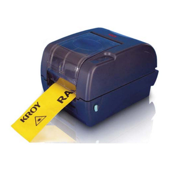
- Page 1 KROY K4452/K4453 THERMAL TRANSFER / DIRECT THERMAL BAR CODE PRINTER USER’S MANUAL...
-
Page 2: Table Of Contents
Contents 1. Introduction ..................1 2. Getting Started ..................1 2.1 Unpacking and Inspection ............1 2.2 Equipment Checklist ..............1 2.3 Printer Parts ................... 3 3. Setup ....................4 3.1 Setting Up the Printer ..............4 3.2 Loading the Ribbon ............... 4 3.3 Loading Label Stock .............. - Page 3 7. LED and Button Operation ............... 41 7.1 LED ....................41 7.2 Button Operation ................. 41...
-
Page 4: Introduction
This printer provides both thermal transfer and direct thermal printing at user selectable speed of: 2.0, 3.0, 4.0 or 5.0 ips for KROY K4452; 2.0 or 3.0 ips for KROY K4453. It accepts roll feed, die-cut, and fan-fold labels for both thermal transfer and direct thermal printing. - Page 5 USB port cable External universal switching power supply Power Cord Label Spindle, fixing tab x2, 1.5” core adapter x2 Ribbon spindle x2 Ribbon rewind spindle paper core If any parts are missing, please contact the Customer Service Department of your purchased reseller or distributor.
-
Page 6: Printer Parts
2.3 Printer Parts Clear Window Ribbon Access Cover LED Indicator Feed Button Printer Top Cover Top Cover Open Lever Fig. 1 Top front view 1. USB Interface 2. Centronics Interface 3. RS-232C DB-9 Interface 4. Power Jack 5. Power Switch Rear Paper Guide Fig. -
Page 7: Setup
3. Setup 3.1 Setting Up the Printer 1. Place the printer on a flat, secure surface. 2. Make sure the power switch is off. 3. Connect the printer to the computer with the Centronics or USB cable. 4. Plug the power cord into the power supply connector at the rear of the printer, and then plug the power cord into a properly grounded receptacle. - Page 8 Make sure both the ribbon access window and the printer top cover are closed prior to powering up the printer. Please follow the steps below to install the ribbon into printer. 1. Push down on the ribbon access window to unlatch and open the cover. 2.
-
Page 9: Loading Label Stock
Rear Hub Fig. 5 Ribbon installation (II) 3.3 Loading Label Stock 1. Insert a 1” label spindle into a paper roll ( * f your paper core is 1 inch, remove the 1.5” core adapter from the fixed tab. If label width is 4 inch wide, two fixing tabs are not required. - Page 10 Lower Cover Fig. 7 Pull the lever to open the cover 3. Place a roll of paper onto the center of the paper roll mount. 4. Feed the paper, printing side face up, through the Teflon bar and the paper guide and pass over the platen.
-
Page 11: External Label Roll Mount Installation (Option)
Printer Top Cover Top Cover Support Paper Roll Mount Teflon Bar Paper Guide Top Cover Open Lever Fig. 8 Label installation (II) 3.4 External Label Roll Mount Installation (Option) 1. Attach an external paper roll mount on the bottom of the printer. Fig. - Page 12 External Paper Roll Mount External Paper Feed Opening Fig. 10 External roll mount label installation (I) 4. Feed the paper, printing side face up, through the paper guide and pass over the platen. 5. Adjust the paper guides to fit the paper width. 6.
-
Page 13: Peel-Off Module Installation (Option)
3.5 Peel-off Module Installation (Option) 1. Open the top cover and remove the front panel from the printer. Front Panel Fig. 12 Remove the front panel 2. Open the top cover and hold it and push down and push backward the top cover support then push backward the top cover. - Page 14 memory card cover. 5. Hold the lower cover to lift up the top cover open levers to separate the lower inner cover and the lower cover. 6. Arrange the cable through the bezel. Connect the peel-off panel cable to the 5-pin socket on printer PCB.
- Page 15 7. Insert the peel-off tenons into the lower inner cover mortises until tenons snap into places. Lower Inner Cover Roller Lower Cover Tenon Mortise Fig. 16 Peel-off panel installation (I) 8. Arrange the lower inner cover back to the lower cover. Peel-off panel Roller...
-
Page 16: Loading The Paper In Peel-Off Mode
3.5.1 Loading the Paper in Peel-off Mode Note: Both thermal paper and plain paper apply for peel-off function but neither PVC nor vynle work at peel-off function. 1. Insert a 1” label spindle into a paper roll. 2. Open the printer top cover by pulling the top cover open levers. The top cover support will hold the printer top cover. - Page 17 5. Feed the paper, printing side facing up, through the paper guide and pass over the platen. 6. Lead the paper through the backing paper opening, beneath the roller, pull the 7. Adjust the paper guide by removing left or right to fit the paper width. Top Cover Top Cover Support Roller...
-
Page 18: Cutter Module Installation (Option)
3.6 Cutter Module Installation (Option) 1. Pull the top cover open levers to open the top cover. 2. Remove the front panel from the lower cover. Lower Cover Fig. 22 Pull the lever to open the cover 3. Open the top cover and hold it and push down and push backward the top cover support then push backward the top cover. - Page 19 6. Unscrew the screw of the memory card cover and remove the memory card cover. Plug in the cutter driver IC at U30 (KROY K4452/4453 series) socket on the main board. 7. Use both thumbs to hold the lower cover and index fingers to lift up the top cover open levers to separate the lower inner cover and the lower cover.
-
Page 20: Loading Label In Cutter Mode
9. Arrange the lower inner cover back to the lower cover. 10. Install the cutter into the niches of the printer. Cutter Niche Fig. 26 Cutter module installation 11. Use a screwdriver to screw whole screws on the lower inner cover and the lower cover. -
Page 21: Instructions To Top Cover Operation
Top Cover Top Cover Support Paper Guide Platen Cutter Fig. 27 Label installation in cutter mode 7. Close the top cover by lifting up the top cover support and close the cover slowly. Fig. 28 Complete label installation in cutter mode 3.7 Instructions to Top Cover Operation Please take care when opening or closing the printer’s top cover by carefully following these instructions. - Page 22 There are two stop positions for the top cover. Position 1 and 2 are indicated on the label below. Note: To hold the cover open at position 1, you must lift the cover higher than the stopping point at position 1 and gently lower the cover to stopping point 1. Do not let the cover free fall! 3.
- Page 23 Fig. 2 Top cover is fully open and ready to close Fig. 3 Use both hands to close the top cover 5. Do not force the cover! If you are not sure if top cover is fixed at stop position, please do not push top cover to close it or the top cover will be damaged.
-
Page 24: Diagnostic Tool
3.8 Diagnostic Tool The Diagnostic Utility is a toolbox that allows users to explore the printer's settings and status; change printer settings; download graphics, fonts, and firmware; create printer bitmap fonts; and to send additional commands to the printer. Using this convenient tool, you can explore the printer status and settings and troubleshoot the printer. -
Page 25: Printer Function (Calibrate Sensor, Ethernet Setup, Rtc Setup
3.8.2 Printer Function (Calibrate sensor, Ethernet setup, RTC setup………) 1. Select the PC interface connected with bar code printer. 2. Click the “Function” button to setting. 3. The detail functions in the Printer Function Group are listed as below. Function Description Calibrate the sensor specified in the Printer Setup Calibrate Sensor... -
Page 26: Setting Ethernet By Diagnostic Utility (Option)
3.9 Setting Ethernet by Diagnostic Utility (Option The Diagnostic Utility is enclosed in the CD disk \Utilities directory. Users can use Diagnostic Tool to setup the Ethernet by RS-232, USB and Ethernet interfaces. The following contents will instruct users how to configure the Ethernet by these three interfaces. -
Page 27: Using Rs-232 Interface To Setup Ethernet Interface
3.9.2 Using RS-232 interface to setup Ethernet interface 1. Connect the computer and the printer with a RS-232 cable. 2. Turn on the printer power. 3. Start the Diagnostic Utility by double clicks on the icon. Note: This utility works with printer firmware V6.00 and later versions. 4. -
Page 28: Using Ethernet Interface To Setup Ethernet Interface
3.9.3 Using Ethernet interface to setup Ethernet interface 1. Connect the computer and the printer to the LAN. 2. Turn on the printer power. 3. Start the Diagnostic Utility by double clicks on the icon. Note: This utility works with printer firmware V6.00 and later versions. 4. - Page 29 The default IP address is obtained by DHCP. To change the setting to static IP address, click “Static IP” radio button then enter the IP address, subnet mask and gateway. Click “Set IP” to take effect the settings. Users can also change the “Printer Name” by another model name in this fields then click “Set Printer Name”...
-
Page 30: Install Memory Card
Remove the screw that fixes the memory card cover. Screw Memory Card Cover Plug in the memory card on main board. K4452/K4453 Model (SD Card) Revert the memory card cover. * Recommended SD card specification. SD card spec SD card capacity Approved SD card manufacturer V1.0, V1.1... - Page 31 V1.0, V1.1 microSD 1 GB Transcend, Panasonic V2.0 SDHC CLASS 4 microSD 4 GB Panasonic V2.0 SDHC CLASS 6 microSD 4 GB Transcend V1.0, V1.1 miniSD 128 MB Transcend, Panasonic V1.0, V1.1 miniSD 256 MB Transcend, Panasonic V1.0, V1.1 miniSD 512 MB Transcend, Panasonic V1.0, V1.1 miniSD 1 GB...
-
Page 32: Power On Utilities
4. Power on Utilities There are six power-on utilities to set up and test printer hardware. These utilities are activated by pressing FEED button and by turning on the printer power simultaneously. The utilities are listed as below: Ribbon sensor calibration;Gap/black mark sensor calibration Gap/black mark sensor calibration;Self-test and dump mode Printer initialization Black mark sensor calibration... -
Page 33: Gap/Black Mark Calibration; ; ; ; Self-Test; ; ; ; Dump Mode
4.2 Gap/Black Mark Calibration; ; ; ; Self-test; ; ; ; Dump Mode While calibrate the gap/black mark sensor, printer will measure the label length, print the internal configuration (self-test) and then enter the dump mode. To calibrate gap or black mark sensor, depends on the sensor setting in the last print job. - Page 34 Self-test Printer will print the printer configuration after gap/black mark sensor calibration. Self-test printout can be used to check if there is any dot damage on the heater element, printer configurations and available memory space. Self-test printout Print head check pattern Model name and F/W version Printed mileage (meter) Firmware checksum...
-
Page 35: Dump Mode
Dump mode Printer will enter dump mode after printing printer configuration. In the dump mode, all characters will be printed in 2 columns as following. The left side characters are received from your system and right side data are the corresponding hexadecimal value of the characters. -
Page 36: Printer Initialization
(5 blinks) solid green Printer configuration will be restore to defaults as below after initialization. Parameter Default setting Speed K4452, 127 mm/sec (5 ips) K4453, 76 mm/sec (3 ips) Density Label Width 4” (101.6 mm) Label Height 4” (101.6 mm) -
Page 37: Black Mark Sensor Calibration
4.4 Black Mark Sensor Calibration Set black mark sensor as media sensor and calibrate the black mark sensor. Please follow the steps as below. 1. Turn off the power switch. 2. Hold on the button then turn on the power switch. 3. - Page 38 3. Release the FEED button when LED becomes solid green. The LED color will be changed as following pattern: Orange red (5 blinks) orange (5 blinks) green (5 blinks) solid green 4. Printer will be interrupted to run the AUTO.BAS program.
-
Page 39: Maintenance
5. Maintenance 5.1 Cleaning This session presents the clean tools and methods to maintain your printer. 1. Please use one of following material to clean the printer. Cotton swab (Head cleaner pen) Lint-free cloth Vacuum / Blower brush 100% ethanol 2. - Page 40 cloth Interior Brush or vacuum As needed Note: Do not touch printer head by hand. If you touch it careless, please use ethanol to clean it. Please use 100% Ethenol. DO NOT use medical alcohol, which may damage the printer head. Regularly clean the print head and supply sensors once change a new ribbon to keep printer performance and extend printer life.
-
Page 41: Troubleshooting
6. Troubleshooting The following guide lists the most common problems that may be encountered when operating this bar code printer. If the printer still does not function after all suggested solutions have been invoked, please contact the Customer Service Department of your purchased reseller or distributor for assistance. -
Page 42: Print Quality
Note: Printer status can be easily shown on the Diagnostic Tool. For more information about the Diagnostic Tool, please refer to the instruction in the software CD disk. 6.2 Print Quality Problem Possible Cause Recovery Procedure Check if interface cable is well Re-connect cable to interface. - Page 43 Adjust the print density and print Check if print density is set properly. speed. Run printer self-test and check the Check print head test pattern if head print head test pattern if there is dot element is damaged. missing in the pattern.
-
Page 44: Led And Button Operation
7. LED and Button Operation 7.1 LED LED Color Description Green/ Solid This illuminates that the power is on and the device is ready to use. Green/ Flash This illuminates that the system is downloading data from PC to memory and the printer is paused. Amber This illuminates that the system is clearing data from printer. - Page 45 Gap/Black Mark 1.Turn off the power switch. Sensor Calibratio, 2. Hold on the button then turn on the power switch. Label Length 3. Release the button when LED becomes amber and blinking. (Any amber will do during the 5 blinks). Measurement, Self Test and enter Dump The LED color will be changed as following order.
- Page 46 Gap Sensor 1. Turn off the power switch. Calibration 2. Hold on the button then turn on the power switch. 3. Release the button when LED turns red/amber after 5 green/amber blinks. (Any red/amber will do during the 5 blinks). The LED color will be changed as following: Amber red (5 blinks)
-
Page 47: Revise History
Revise History Date Content 2009/10/14 *Revise section 3.8 *Add section 3.9 2010/11/23 * Revise section 1, 2.3 and 3.1... - Page 48 For sales within the United Kingdom, mainland Europe, the Middle East and Africa please contact: Kroy Europe Limited Unit B7, Worton Drive, Worton Grange, Reading, Berkshire RG2 0LZ England Tel: +44 (0) 118 986 5200 Fax: +44 (0) 118 986 5205 Website: www.kroyeurope.com...
Need help?
Do you have a question about the K4452 and is the answer not in the manual?
Questions and answers