Table of Contents
Advertisement
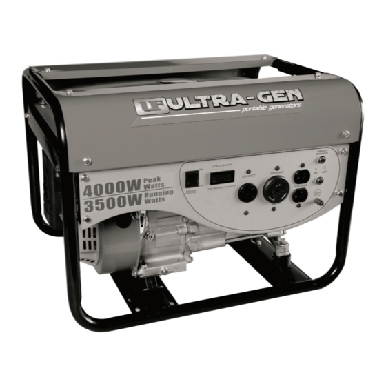
4000 Starting Watts / 3500 Rated Watts
Recoil Start
PORTABLE GENERATOR
SAVE THESE INSTRUCTIONS
Important Safety Instructions
are included in this manual.
OWNER'S MANUAL & OPERATING INSTRUCTIONS
MODEL NUMBER
UF-51-940034
MADE IN CHINA
REV UF-51-940034-20120629
10006 Santa Fe Springs Road
Santa Fe Springs CA 90670
USA / 1-877-338-0999
www.championpowerequipment.com
Advertisement
Table of Contents

Related Manuals for Ultra-Gen UF-51-940034


Summary of Contents for Ultra-Gen UF-51-940034
-
Page 1: Recoil Start
4000 Starting Watts / 3500 Rated Watts Recoil Start PORTABLE GENERATOR MODEL NUMBER UF-51-940034 10006 Santa Fe Springs Road SAVE THESE INSTRUCTIONS Santa Fe Springs CA 90670 Important Safety Instructions USA / 1-877-338-0999 MADE IN CHINA are included in this manual. REV UF-51-940034-20120629 www.championpowerequipment.com... - Page 2 Have questions or need assistance? Do not return this product to the store! WE ARE HERE TO HELP! Visit our website: www.championpowerequipment.com for more info: • Product Info & Updates • Tech Bulletins • Frequently Asked Questions • Product Registration –...
-
Page 3: Table Of Contents
UF-51-940034 4000 Starting Watts / 3500 Rated Watts Recoil Start PORTABLE GENERATOR TABLE OF CONTENTS Introduction . . . . . . . . . . . . . . . . . . . . . . . . . . . . -
Page 4: Introduction
. Champion Power Equipment Support 1-877-338-0999 Model Number UF-51-940034 Serial Number Date of Purchase Purchase Location For Oil Type see ‘Add Engine Oil‘ section . For Fuel Type see ‘Add Fuel‘ section . REV UF-51-940034-20120629... -
Page 5: Manual Conventions
. Please call our help line at 1-877-338-0999. situation which, if not avoided, could result in death or serious injury . CAUTION CAUTION indicates a potentially hazardous situation which, if not avoided, may result in minor or moderate injury . REV UF-51-940034-20120629... -
Page 6: Safety Rules
Inform your electricity provider immediately if you or anyone in your household depends on electrical euipment to live . Inform your electrical provider immediately if a loss of power would cause you or anyone in your household to experience a medical emergency . REV UF-51-940034-20120629... - Page 7 – Electrical output is lost – Equipment sparks, smokes or emits flames A spark arrestor may be required . The operator – Equipment vibrates excessively should contact local fire agencies for laws or regulations relating to fire prevention requirements . REV UF-51-940034-20120629...
-
Page 8: Controls And Features
Fuel Valve – Used to turn fuel supply on and off to Power Panel – See “Power Panel” section . engine . Air Filter – Protects the engine by filtering dust and debris from the intake air . REV UF-51-940034-20120629... -
Page 9: Power Panel
60 Hz electrical loads . (NEMA L5-30R) – May be used to supply electrical Ground Terminal – Consult an electrician for local power for the operation of 120 Volt AC, 30 Amp, grounding regulations . single phase 60 Hz electrical loads . REV UF-51-940034-20120629... -
Page 10: Parts Included
UF-51-940034 ENGLISH CONTROLS ANd FEATURES Parts Included Your UF-51-940034 Gasoline Powered Generator ships with the following parts: Spark Arrester Kit – Spark Arrester . . . . . . . . . . . . . . . . . . . . . . . . . -
Page 11: Assembly
. CAUTION Failure to install the spark arrester may result in an increased risk of fire . REV UF-51-940034-20120629... -
Page 12: Add Engine Oil
. 2 . Remove oil fill cap/dipstick to add oil . 3 . Add up to 0 .63 qt . (0 .6 L) of oil and replace oil fill cap/dipstick . REV UF-51-940034-20120629... -
Page 13: Add Fuel
DO NOT overfill the fuel tank . DO NOT light cigarettes or smoke when filling the fuel tank . WARNING Pouring fuel too fast through the fuel screen may result in blow back of fuel at the operator while filling . REV UF-51-940034-20120629... -
Page 14: Operation
If the engine starts but does not run make certain that the generator is on a flat, level surface . The engine is equipped with a low oil sensor that will prevent the engine from running when the oil level falls below a critical threshold . REV UF-51-940034-20120629... -
Page 15: Connecting Electrical Loads
4 . Turn the Fuel Valve to the “OFF” position . Important: If the generator will be moved or stored turn the Fuel Valve to the “OFF“ position and ensure the Ignition Switch on the Power Panel is in the “OFF“ position . REV UF-51-940034-20120629... -
Page 16: Operation At High Altitude
. For operation at lower elevations, the standard main jet must be used . Operating the engine with the wrong engine configuration at a given altitude may increase its emissions and decrease fuel efficiency and performance . REV UF-51-940034-20120629... -
Page 17: Maintenance And Storage
5 . Squeeze in a clean, absorbent cloth to remove all 6 . Dispose of used oil at an approved waste management facility . excess oil . 6 . Place the filter in the assembly . 7 . Reattach the air filter cover and snap in place . REV UF-51-940034-20120629... -
Page 18: Spark Arrester
The air-fuel mixture is not adjustable . Tampering with the governor can damage your generator and your electrical devices and will void your warranty . CPE recommends that you contact our service line at 1-877-338-0999 for all other service and/or adjustment needs . REV UF-51-940034-20120629... -
Page 19: Generator Maintenance
. Crank the engine slowly to distribute the oil and lubricate the cylinder . 8 . Reattach the spark plug . 9 . Store the unit in a clean, dry place out of direct sunlight . REV UF-51-940034-20120629... -
Page 20: Specifications
10% by volume . Use 4-Cycle automotive oil . Oil capacity is 0 .63 qt . (0 .6 L) . Please reference the following chart for recommended oil types for use in the generator . REV UF-51-940034-20120629... -
Page 21: Wiring Diagram
UF-51-940034 ENGLISH SPECIFICATIONS Wiring diagram REV UF-51-940034-20120629... -
Page 22: Parts Diagram
UF-51-940034 ENGLISH SPECIFICATIONS Parts diagram REV UF-51-940034-20120629... -
Page 23: Parts List
AC .25A Breaker GB5789 M6x8 Flange Bolt M6×8 ST02FD-05202003 Control Box ST168FD-1160002-B Pipe,Fuel ST188FD-1020001 Ring ST188FD-1070006A Clip GB97 .1 5 Washer φ5 ST02FD-04160000 Fuel Cock GB818 M5×38 Screw M5×38 504 .071000 .35(B) Fuel Tank ST02FD-04100010 Mount Vibration, Fuel Tank REV UF-51-940034-20120629... -
Page 24: Engine Parts Diagram
UF-51-940034 ENGLISH SPECIFICATIONS Engine Parts diagram REV UF-51-940034-20120629... -
Page 25: Engine Parts List
Bolt,Governor arm ST168FD-2-1131000- Carburetor GB5789-86-FB6-25 Flange bolt 6x25 ST168FD-1130005-CPE Gasket,carburetor ST160F-1123000-G Ignition coil GB97 .1 6 Washerφ6 152FMD-1001007 Dowel pin 10x16 ST168FD-2-1131000-17 Standard main jet GB5789-86-FB8-55 Flange bolt 8x55 ST168F-2-1131000-17 Altitude Main Jet ST168FD-1090005-G Cover,Air cleaner ST168FD-1090004 Element REV UF-51-940034-20120629... -
Page 26: Troubleshooting
Review load and adjust . See “Power Management” Faulty cords or device Check for damaged, bare or frayed wires . Replace defective device For further technical support: Technical Service Mon – Fri 8:30 AM – 5:00 PM (PST/PDT) Toll Free: 1-877-338-0999 tech@championpowerequipment .com REV UF-51-940034-20120629... -
Page 27: Warranty
Technical Service generator’s limits, modified, installed improperly or Mon – Fri 8:30 AM – 5:00 PM (PST/PDT) connected incorrectly to any electrical component . Toll Free: 1-877-338-0999 tech@championpowerequipment .com 24/7 Tech Support: 1-562-204-1188 REV UF-51-940034-20120629... - Page 28 Champion Power Equipment, Inc. (CPE), The California Air Resources Board (CARB) and the United States Environment Protection Agency (U.S. EPA.) Emission Control System Warranty Your Champion Power Equipment (CPE) engine complies with both the U.S. EPA and state of California Air Resources Board (CARB) emission regulations.
- Page 29 EMISSION CONTROL SYSTEM WARRANTY The following are specific provisions relative to your Emission Control System Warranty Coverage. 1. APPLICABILITY: This warranty shall apply to 1995 and later model year California small off-road engines (for other states, 1997 and later model year engines). The ECS Warranty Period shall begin on the date the new engine or equipment is delivered to its original, end-use purchaser, and shall continue for 24 consecutive months thereafter.
- Page 30 EMISSION-RELATED PARTS INCLUDE THE FOLLOWING: (using those portions of the list applicable to the engine) Systems covered by this Parts Description warranty Fuel Metering System Fuel regulator, Carburetor and internal parts Air Induction System Air cleaner, Intake manifold Ignition System Spark plug and parts, Magneto ignition system Exhaust System Exhaust manifold, catalytic converter...
Need help?
Do you have a question about the UF-51-940034 and is the answer not in the manual?
Questions and answers