Advertisement
Before You Start
A. Is this product compatible with the vehicle?
• See Appendix A - Known Incompatible Vehicles (page 5)
and Appendix E - Identification and Connection Chart (pages
6-7) to see if your vehicle is listed. If not, check www.pac-audio.
com for an updated list of compatible vehicles.
B. Is this product compatible with the head unit?
• Ensure that the new head unit is capable of being operated with a remote control, and that it responds to the
remote control provided with it.
• The head unit must accept a remote control with the common carrier frequency range of 38 – 40Khz in order to
work with the SWI-X.
Note: Certain head units will not work with the SWI-X. See Appendix B - Known Incompatible Aftermarket Head
Units (page 5).
C. Prepare for the installation.
• If possible, install the SWI-X while you are installing the new head unit. Keep in mind you may need to plug in the
factory stereo to locate certain wires; therefore do not complete the head unit installation until the SWI-X is working
properly.
• Plan a general installation location for both the SWI-X LED and the control body. Keep in mind that the supplied
wire harness is two feet long, and the IR harness is four feet long.
• Use a multimeter or approved measuring device for checking vehicle circuits.
Wiring Connections
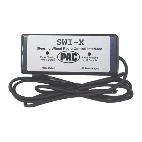
SWI-X
Universal Steering Wheel Control Interface
Step 1.
Connect the BLACK
wire to ground (-).
Verification: Wire
or location registers
a constant (-) when
probed.
Step 3.
Connect the appropriate interface wire (WHITE, YELLOW, ORANGE or
GREEN).
• Refer to the Appendix E - Identification and Connection Chart (pages
6-7). Locate the vehicle and note the SWC wire color in the "Interface Wire
Color" column.
• Note the vehicle wire color and location information in the "Identification"
column.
Note: You will only connect ONE of these wires. Cut and insulate the un-
used wires.
• Connect the wire as indicated.
Installation Instructions
Step 2.
Connect the RED wire
to switched +12V.
Verification: Wire reg-
isters +12V when the
ignition key is turned
to the ACC or ON posi-
tions.
Advertisement
Table of Contents

Subscribe to Our Youtube Channel
Related Manuals for PAC SWI-X


Summary of Contents for PAC SWI-X
-
Page 1: Installation Instructions
C. Prepare for the installation. • If possible, install the SWI-X while you are installing the new head unit. Keep in mind you may need to plug in the factory stereo to locate certain wires; therefore do not complete the head unit installation until the SWI-X is working properly. - Page 2 BLUE wire. Programming the SWI-X to Work With the Vehicle IMPORTANT! Some steps of the programming instructions must be completed within a certain number of seconds following the previous step. Review the complete instruction before beginning the programming sequence.
- Page 3 Programming the SWI-X to Control the Head Unit IMPORTANT! Some steps of the programming instructions must be completed within a certain number of seconds following the previous step. Review the complete instruction before beginning the programming sequence. Step 11. LEDs will flash to...
-
Page 4: Final Installation
Testing the SWI-X Hold the SWI-X infrared emitter (clear blue light at the end of the four-foot wire) close to the head unit and test each function of the steering wheel controls. The right LED on the SWI-X will flash indicating it is sending an IR command... - Page 5 Appendix A: Known Incompatible Vehicles Vehicle Make(s) Year(s) Model(s) All with factory-activated cellular phones All with 5-volt SWC data wire at the steering column 2002-2003 5-Series w/navigation Mercedes-Benz All vehicles Toyota All-2003 Sienna Volkswagen 2002-up All vehicles Appendix B: Known Incompatible Aftermarket Head Units Head Unit Make(s) Model(s)
-
Page 8: Appendix F: Troubleshooting Guide
Appendix F: Troubleshooting Guide No power / won’t go into programming mode: • Check Red wire connection and fuse. Make sure INTERFACE is connected to switched 12V+. • Make sure vehicle ignition is on. Won’t program radio commands: • Make sure version number and IR Extended mode setting are programmed before attempting to program radio commands. The right LED of the INTERFACE will flash the programmed version number when power is applied.
Need help?
Do you have a question about the SWI-X and is the answer not in the manual?
Questions and answers