
Related Manuals for Superior O-360 SERIES


Summary of Contents for Superior O-360 SERIES
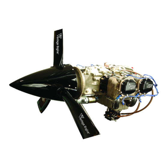
- Page 1 O-360 & IO-360 SERIES ENGINES INSTALLATION & OPERATION MANUAL 621 South Royal Lane, Suite 100 / Coppell, TX 75019 / 800-277-5168 www.superior-air-parts.com P/N SVIOM01 Revision A, March, 2004 FAA Approved...
- Page 2 EXCEED THE ORIGINAL COST OF THE ENGINE OR ACCESSORY. Written notice of any warranty claim must be submitted to Superior within thirty (30) days of a suspected defect in material or workmanship and the engine, accessory or part must be made available for Superior's inspection within thirty (30) days after the claim has been made.
-
Page 3: Table Of Contents
2. Special Tools And Equipment 3. Break In Procedures 4. General Inspection Check 5. Daily Pre Flight Inspection Chapter 6 Normal Operating Procedures 1. General 2. Engine Operation And Limits 3. Operation Instructions © March 2004 Superior Air Parts Inc. - Page 4 Engine Preservation And Storage 1. Temporary Storage 2. Indefinite Storage 3. Inspection Procedures 4. Returning An Engine To Service After Storage Appendix A O-360 Model Specification Data Appendix B IO-360 Model Specification Data © March 2004 Superior Air Parts Inc.
-
Page 5: Revision History
WARNING It is the users responsibility to insure that this is the current revision of this manual. Do not perform any operation, installation, maintenance, or other procedure until confirming this manual is current. © March 2004 Superior Air Parts Inc. -
Page 6: List Of Figures
#1 Dynafocal Mount Dimensions #2 Dynafocal Mount Dimensions Conical Mount Dimensions Limit and Ultimate Engine Forces Engine Mount Forcing Function for Engine Startup and Shutdown Engine Mount Forcing Function for Steady State Conditions © March 2004 Superior Air Parts Inc. - Page 7 Number Manufacturer’s General Specifications Manufacturer’s Physical Specifications Views of the Engine Accessory Drive Data Lord Engine Mounts for Superior Vantage Engines Limit and Ultimate Engine Mount Loads Instrumentation Connections Normal Starting Procedures Starting A Flooded Engine Ground Running / Fixed Wing Warm-Up...
-
Page 8: Introduction
Superior Vantage Engine Superior. Upon approval of an installation to an airframe and to describe its’ operational design, Superior will provide a letter that states characteristics. Its purpose is to provide in part that the installation design is acceptable... -
Page 9: Obtaining Service Information
All Vantage Series Engine manuals and service www.unisonindustries.com information may also be purchased by contacting: www.skytecair.com Superior Air Parts www.precisionairmotive.com 621 South Royal Lane, Suite 100 Coppell, Texas 75019 www.aeroaccessories.com or call: 972-829-4600 © March 2004 Superior Air Parts Inc. -
Page 10: Chapter 1 Engine Description
Figure 1-1. specified. Accessory drive rotation direction is Figure 1-1 • Model Number Designation © March 2004 Superior Air Parts Inc. Chapter 1 • Engine Description... - Page 11 Accessory Package Ignition System Fuel System Carbureted Fuel Injected Unison Magnetos Precision Carburetor Precision Fuel Injection Digit Power Rating: Piston Compression Ratio Cylinder Type 8.5:1 *For Future Use © March 2004 Superior Air Parts Inc. Chapter 1 • Engine Description...
-
Page 12: Engine Components General Description
Bore, inches 5.125 Stroke, inches 4.375 Displacement cubic inches 361.0 Compression Ratio 8.5:1 Firing Order 1-3-2-4 Spark timing °BTDC Propeller drive ratio Propeller drive rotation Clockwise (viewed from rear) © March 2004 Superior Air Parts Inc. Chapter 1 • Engine Description... - Page 13 Figure 1-6 p. 9 IO-360 Engine Left Side View Figure 1-7 p. 10 IO-360 Engine Top View Figure 1-8 p. 11 IO-360 Engine Rear View Figure 1-9 p. 12 © March 2004 Superior Air Parts Inc. Chapter 1 • Engine Description...
- Page 14 CHT PROBE LOCATION PRIMING (TYPICAL EACH HEAD) SYSTEM ALTERNATOR & BELT NOT PROVIDED WITH ENGINE STARTER THROTTLE LEVER FUEL LINE CARBURETOR Figure 1-2 • O-360 Engine Front View © March 2004 Superior Air Parts Inc. Chapter 1 • Engine Description...
- Page 15 ASSEMBLY HARNESS MAGNETO FUEL PUMP PRIMING SPARK PLUG FUEL SYSTEM LINE STARTER MIXTURE LEVER INDUCTION OIL SUMP SYSTEM ASSEMBLY CARBURETOR Figure 1-3 • O-360 Engine Left Side View © March 2004 Superior Air Parts Inc. Chapter 1 • Engine Description...
- Page 16 Installation & Operation Manual O-360 and IO-360 Series Engines INTER-CYLINDER BAFFLE SPARK PLUG MAGNETO MAGNETO OIL FILTER Figure 1-4 • O-360 Engine Top View © March 2004 Superior Air Parts Inc. Chapter 1 • Engine Description...
- Page 17 FUEL PUMP OIL DRAIN PLUG COMMON PRIMER LINE SOURCE FUEL PUMP INLET FUEL LINE OIL SUCTION SCREEN FUEL MIXTURE THROTTLE LEVER LEVER Figure 1-5 • O-360 Engine Rear View © March 2004 Superior Air Parts Inc. Chapter 1 • Engine Description...
- Page 18 SPARK PLUG FUEL INJECTOR CHT PROBE LOCATION (TYPICAL EACH HEAD) ALTERNATOR & BELT STARTER NOT PROVIDED WITH ENGINE FUEL INJECTION SERVO Figure 1-6 • IO-360 Engine Front View © March 2004 Superior Air Parts Inc. Chapter 1 • Engine Description...
- Page 19 STARTER SUPPORT OIL FILTER ASSEMBLY WIRING HARNESS MAGNETO FUEL PUMP STARTER FUEL LINE SPARK PLUG OIL SUMP FUEL INJECTION SERVO Figure 1- 7 • IO-360 Engine Left Side View © March 2004 Superior Air Parts Inc. Chapter 1 • Engine Description...
- Page 20 Installation & Operation Manual O-360 and IO-360 Series Engines FUEL INJECTION MANIFOLD FUEL INJECTIOR Figure 1- 8 • IO-360 Engine Top View © March 2004 Superior Air Parts Inc. Chapter 1 • Engine Description...
- Page 21 FUEL PUMP INLET DIAPHRAGM FUEL OIL DRAIN PLUG PUMP OIL SUCTION SCREEN OIL DRAIN PLUG THROTTLE CONTROL LEVER MIXTURE CONTROL LEVER Figure 1- 9 • IO-360 Engine Rear View © March 2004 Superior Air Parts Inc. Chapter 1 • Engine Description...
-
Page 22: Features And Operating Mechanisms
Fuel Systems camshaft is located above and parallel to the crankshaft. The camshaft actuates hydraulic Carbureted - Superior Air Parts O-360 engines lifters that operate the valves through push rods are equipped with a float type carburetor The and valve rockers. -
Page 23: Chapter 2 Airworthiness Limitations
F.A.A. Approved Mandatory Service Bulletins issued after the date of certification, the O-360 and IO-360 engine series do not have any inspection-related or replacement time-related procedures required for type certification. © March 2004 Superior Air Parts Inc. Chapter 2 • Airworthiness Limitations... -
Page 24: Chapter 3 Aircraft / Engine Integration Considerations
The term “maximum discussion of design practices to be considered attainable pressure” as used here refers to an during the integration of a Superior Vantage air source that provides maximum intake air engine with an airframe and propeller. These pressure, (including ram air effects) while discussions should be used IN ADDITION TO minimizing restrictions and flow losses. - Page 25 Intake air flow that is supplied to the carburetor. requirements of a Superior Vantage Engine are defined in Figure 1 of the Model Specification Chapter 3 • Aircraft / Engine ©...
- Page 26 Chapter 3 • Aircraft / Engine © March 2004 Superior Air Parts Inc. Integration Considerations...
-
Page 27: Fuel System
Superior Air Parts recommends the use of fuel engine detonation under certain conditions. flow meters as an aid to the pilot for proper engine management. - Page 28 The carburetor system is part of the Superior Vantage Engine and therefore certified as part of the engine. No one may make significant changes to either flow settings or mechanical linkages without prior approval by Superior.
- Page 29 Locate the fuel boost pump as close to the fuel tank as possible. Non-metallic fuel system components should be manufactured from materials that are known to be compatible with auto fuels. Chapter 3 • Aircraft / Engine © March 2004 Superior Air Parts Inc. Integration Considerations...
-
Page 30: Engine Cooling
Installation & Operation Manual O-360 and IO-360 Series Engines 4. ENGINE COOLING The lubricating oil for Superior Vantage Engines engine cooling system design must be cooled by means of an air-to-fluid heat significantly effect both performance exchanger. Typically, this heat exchanger is longevity of an aircraft engine installation. - Page 31 Therefore, cooler sizing calculations should be made with the air density appropriate for the maximum intended altitudes of the installation. Chapter 3 • Aircraft / Engine © March 2004 Superior Air Parts Inc. Integration Considerations...
-
Page 32: Exhaust
For Superior Vantage Engines with 4 cylinders, with each other. While these systems are crossover exhaust systems should couple... - Page 33 Also, welds should be of collector, can increase flow losses and should superior quality to prevent metallurgical or be avoided. fatigue failure and subsequent exhaust leaks. Chapter 3 • Aircraft / Engine © March 2004 Superior Air Parts Inc. Integration Considerations...
- Page 34 O-360 and IO-360 Series Engines (6.) EGT Probes D. Exhaust Gaskets Exhaust gas temperature (EGT) probes are Superior recommends the use of metal gaskets commonly added to engine installations to in the installation of exhaust systems. Metal provide engine management information to the gaskets improve the seal to the exhaust port pilot.
-
Page 35: Lubrication System
Superior recommends the use of high quality installations. However, provisions exist to attach 100% mineral oil during the break-in period. an aerobatic oil system to the Superior Vantage After engine break-in, high quality ashless Engine if desired. For more information... - Page 36 The oil drain may be connected into a cylinder also add to the potential for aeration during high head drain back tube or other location as altitude flight. approved by Superior Air Parts. Chapter 3 • Aircraft / Engine © March 2004 Superior Air Parts Inc. Integration Considerations...
- Page 37 Bearing Splash Oil To Pistons, Cams, Etc. Cyl#1 Cyl #1 Piston Crankpin Cooling Nozzle (If installed) To Prop Governor Figure 3-1 • Oil System Schematic Chapter 3 • Aircraft / Engine © March 2004 Superior Air Parts Inc. Integration Considerations...
-
Page 38: Propeller Attachment
SAE Type 2 Propeller Flange per AS127 with ½” bolts. The nut and bolt specifications, torque specs methodology, size and use of safety wire, etc. specified propeller manufacturer. Chapter 3 • Aircraft / Engine © March 2004 Superior Air Parts Inc. Integration Considerations... -
Page 39: Electrical System
The engine electrical system is responsible for The firing order and ignition system wiring three (3) primary duties. They are ignition, diagram for the Superior Vantage Engine is starting and power supply to the aircraft. provided in Figure 3-2. Superior Vantage Engines are supplied with two (2) magnetos that have been properly timed at B. -
Page 40: Firing Order
Installation & Operation Manual O-360 and IO-360 Series Engines Firing Order Clockwise Rotation 1−3−2−4 Ignition Wiring Diagram Figure 3-2 • Ignition Wiring Diagram Chapter 3 • Aircraft / Engine © March 2004 Superior Air Parts Inc. Integration Considerations... -
Page 41: Engine Controls
Superior Vantage Engines. (11.) Superior recommends the use of ball joints Many methods may be used to accomplish this or similar apparatus at the lever attachment as long as the following issues are addressed. - Page 42 Superior Vantage Engines. The control design of the engine. Figure 1-5 illustrates the common should address the same issues as listed above primer line source for a typical Superior Vantage for the throttle and mixture controls. carbureted engine. Note: Manual primer pumps should include a positive lock feature to prevent the pump from inadvertently actuating during flight.
-
Page 43: Engine Accessories
Clockwise Fuel Pump –Plunger Operated 0.500 : 1 Reciprocating Note: Direction of rotation for accessories is listed as viewed from the rear of the engine. Chapter 3 • Aircraft / Engine © March 2004 Superior Air Parts Inc. Integration Considerations... - Page 44 Installation & Operation Manual O-360 and IO-360 Series Engines CRANKCASE SIDEVIEW MOUNTING PAD Figure 3-3 • Alternator Mounting Pad Chapter 3 • Aircraft / Engine © March 2004 Superior Air Parts Inc. Integration Considerations...
-
Page 45: Engine Mounting
Mounting Kit part number for the Superior minimum obstruction to cooling airflow, weight, Vantage Engine mount options. Table 3-2 • Lord Engine Mounts for Superior Vantage Engines Superior Vantage Mount Style Figure Lord Mounting Kit... - Page 46 Installation & Operation Manual O-360 and IO-360 Series Engines Figure 3-4 • #1 Dynafocal Mount Dimensions Figure 3-5 • #2 Dynafocal Mount Dimensions Chapter 3 • Aircraft / Engine © March 2004 Superior Air Parts Inc. Integration Considerations...
- Page 47 B. Engine CG and Moment of Inertia C. Engine Mount Design Loads The engine weight and location of the center of Superior Vantage Engines are certified to meet gravity are specified in Table 7 of the Model the requirements of FAR 23 Acrobatic Category Specification Data.
- Page 48 (FAR 23) includes the use of several Factors of output torque of the engine at maximum rated Safety. When performing the engine installation speed plus design factors as required by 14CFR design for a Superior Vantage Engine, the Part When performing...
- Page 49 Data is presented for startup and and Superior has designed the Vantage Engine shutdown sequences in Figure 3-8 and steady for state of the art isolation systems. However, state power settings in Figure 3-9.
- Page 50 Torsion Bending - Horizontal Bending - Vertical 5000 10000 15000 20000 25000 Frequency (Hz) Figure 3-9 • Engine Mount Forcing Function for Steady State Conditions Chapter 3 • Aircraft / Engine © March 2004 Superior Air Parts Inc. Integration Considerations...
-
Page 51: Chapter 4 Engine Installation
Remove the shipping plugs installed in the upper spark plug holes and inspect the cylinder bores for rust or contamination. Contact Superior if any abnormal condition is noted. © March 2004 Superior Air Parts Inc. Chapter 4 • Engine Installation... -
Page 52: Installation Of Engine
Standard Tach Drive Connection: 5/32 Square Drive Fig. 1-5 Fig. 1-9 Drive Socket with 7/8-18 UNS Cap Threads App A App B Fuel Pressure 1/8-27 NPT Table 3 Table 3 © March 2004 Superior Air Parts Inc. Chapter 4 • Engine Installation... -
Page 53: Chapter 5 Special Procedures
EXAMINATION CAUSE FURTHER top overhaul or major engine overhaul, break-in DAMAGE TO A DISABLED COMPONENT is critical. Always refer to the latest Superior AND POSSIBLE INJURY TO PERSONNEL. Service Data on Break-In instructions. MAKE SURE THOROUGH INSPECTION AND TROUBLESHOOTING PROCEDURES ACCOMPLISHED. - Page 54 (eg; high density altitudes) “Full Rich” operation may not be practical. In this event, substitute the requirement of “Full Rich” as discussed in this chapter with the “richest practical setting”. © March 2004 Superior Air Parts Inc. Chapter 5 • Special Procedures...
-
Page 55: General Inspection Check
(9.) Check controls for general condition, security, and freedom of travel and operation. (10.) Induction system air filter should be inspected and serviced in accordance with the airframe manufacturer's recommendations. © March 2004 Superior Air Parts Inc. Chapter 5 • Special Procedures... -
Page 56: Chapter 6 Normal Operating Procedures
3. OPERATION INSTRUCTIONS Note: The Vantage series engines have been This section has the necessary procedures to carefully run-in by Superior Air Parts, but operate the O-360 and IO-360 series engines. requires further break-in until oil consumption Complying with these instructions will optimize has stabilized. - Page 57 Reid Vapor Pressure (RVP) tester, such as a Hodges Volatility Tester (which gives a go or no-go reading), is also recommended. © March 2004 Superior Air Parts Inc. Chapter 6 • Normal Operating Procedures...
- Page 58 HOT STARTS USE THE SAME PROCEDURE AS A NORMAL START WITH THE EXCEPTION OF PRIMING – OMIT PRIMING © March 2004 Superior Air Parts Inc. Chapter 6 • Normal Operating Procedures...
- Page 59 45 seconds to rise to the minimum of 20 psi. If a full minute goes by without reaching a proper oil pressure setting, the engine should be shut down and inspected. © March 2004 Superior Air Parts Inc. Chapter 6 • Normal Operating Procedures...
- Page 60 4. Engine is warm enough for take-off when the oil temperature exceeds 75°F and the engine does not hesitate with throttle advancement. © March 2004 Superior Air Parts Inc. Chapter 6 • Normal Operating Procedures...
- Page 61 Note: Minor spark plug fouling can usually be cleared with magnetos on and holding throttle at 2200 RPM. 6. Mixture – Move toward idle cutoff until RPM peaks and hold for ten seconds. Return mixture to full rich. © March 2004 Superior Air Parts Inc. Chapter 6 • Normal Operating Procedures...
- Page 62 Difference between the drop-offs of the two magnetos should never exceed 50 RPM. If a smooth drop-off past normal is observed it is usually a sign that the mixture is either too lean or too rich. © March 2004 Superior Air Parts Inc. Chapter 6 • Normal Operating Procedures...
- Page 63 Regardless of the instruments used in monitoring the mixture, the following general rules should be observed by the operator of Superior Air Parts aircraft engines. 3. Never exceed the maximum red line cylinder head temperature limit of 500°F.
- Page 64 2. Idle until there is a definite reduction in cylinder head temperature. 3. Move mixture control to "Idle Cut-Off". 4. When engine stops, turn off switches. *Omit step one for Rotorcraft shut down. © March 2004 Superior Air Parts Inc. Chapter 6 • Normal Operating Procedures...
- Page 65 This will be restored as the ice is melted. carburetor heat control should then be returned to the "Cold" or "Off" position. © March 2004 Superior Air Parts Inc. Chapter 6 • Normal Operating Procedures...
-
Page 66: Chapter 7 Abnormal Operating Procedures
Engine Not Able to Develop Full Power Rough Engine Operation Low Power and Engine Runs Rough Low Oil Pressure On Engine Gage High Oil Temperature Excessive Oil Consumption © March 2004 Superior Air Parts Inc. Chapter 7 • Abnormal Operating Procedures... - Page 67 Incorrect idle adjustment Adjust throttle stop to obtain correct idle. Uneven cylinder compression Check condition of piston rings and valve seats Faulty ignition system Check entire ignition system © March 2004 Superior Air Parts Inc. Chapter 7 • Abnormal Operating Procedures...
- Page 68 Clean points. Check internal timing of magnetos. Defective ignition wire Check wire with electric tester. Replace defective wire. Defective spark plug terminal connectors Replace connectors on spark plug wire. © March 2004 Superior Air Parts Inc. Chapter 7 • Abnormal Operating Procedures...
-
Page 69: Low Oil Pressure On Engine Gage
Use mineral base oil. Climb to cruise altitude at full power and operate at 75% cruise power setting until oil consumption stabilizes. See Break-In Procedures, Special Procedures Section Chapter 5. © March 2004 Superior Air Parts Inc. Chapter 7 • Abnormal Operating Procedures... -
Page 70: Chapter 8 Servicing Requirements
(2) (Semi-Synthetic Oils may be used after break-in provided that they meet MIL-L-22851 or J-1899. Table 8-2 • Oil Sump Capacity Maximum Oil Capacity 8 U.S. Quarts Minimum Safe Quantity in the sump 2.5 U.S. Quarts © March 2004 Superior Air Parts Inc. Chapter 8 • Servicing Requirements... -
Page 71: Fuels
91 minimum octane premium grade fuel. Table 8-3 • Minimum Octane Fuels Minimum Octane Aviation Grade Motor Fuel 91/98 Avgas 91 (R+M/2) (Lead Optional) (No Alcohol) © March 2004 Superior Air Parts Inc. Chapter 8 • Servicing Requirements... -
Page 72: Chapter 9 Engine Preservation And Storage
BEFORE MOVING THE PROPELLER DO THE flange: “Do Not Turn Propeller – Engine FOLLOWING: Preserved – (Preservation Date)” (A.) DISCONNECT ALL SPARK PLUG LEADS. © March 2004 Superior Air Parts Inc. Chapter 9 • Engine Preservation & Storage... -
Page 73: Indefinite Storage
B. The cylinder bores of all engines prepared PROPELLER BLADES WHILE for indefinite storage must be re-sprayed TURNING THE PROPELLER. with corrosion preventive mixture every 90 days. © March 2004 Superior Air Parts Inc. Chapter 9 • Engine Preservation & Storage... -
Page 74: Returning An Engine To Service After Storage
DOWNS ARE INSTALLED AND VERIFY THAT THE CABIN DOOR LATCH IS OPEN. (F.) DO NOT STAND WITHIN THE ARC OF PROPELLER BLADES WHILE TURNING THE PROPELLER. © March 2004 Superior Air Parts Inc. Chapter 9 • Engine Preservation & Storage... - Page 75 O-360 SERIES ENGINE MODEL SPECIFICATION DATA APPENDIX A...
-
Page 76: Appendix A O-360 Model Specification Data
Oil Pressure Limits Engine Accessories Engine Weight & Location of Center of Gravity Engine Moment of Inertia Oil Temperature Limits Fuel Grade Requirements Operating Conditions Accessory Temperature Limits Appendix A • O-360 Model © March 2004 Superior Air Parts Inc. Specification Data... - Page 77 Superior Vantage O/IO-360 Series 20 In-Hg 1900 2000 2100 2200 2300 2400 2500 2600 2700 2800 Engine Speed (RPM) Figure 1 • Induction Air Flow Requirements Appendix A • O-360 Model © March 2004 Superior Air Parts Inc. Specification Data...
- Page 78 Model Specification Data O-360 Series Engine Inter-Cylinder Baffle Performance Superior Vantage O/IO-360 Series 2500 2000 1500 1000 Baffle Differential Pressure (In H Figure 2 • Inter-Cylinder Baffle Performance Appendix A • O-360 Model © March 2004 Superior Air Parts Inc. Specification Data...
- Page 79 Model Specification Data O-360 Series Engine Figure 3a • Location of Engine Center of Gravity - Horizontal Appendix A • O-360 Model © March 2004 Superior Air Parts Inc. Specification Data...
- Page 80 Model Specification Data O-360 Series Engine Figure 3b • Location of Engine Center of Gravity - Vertical Appendix A • O-360 Model © March 2004 Superior Air Parts Inc. Specification Data...
- Page 81 Model Specification Data O-360 Series Engine Figure 4 • O-360 Installation Drawing Front View Appendix A • O-360 Model © March 2004 Superior Air Parts Inc. Specification Data...
- Page 82 Model Specification Data O-360 Series Engine Figure 5 • O-360 Installation Drawing Top View Appendix A • O-360 Model © March 2004 Superior Air Parts Inc. Specification Data...
- Page 83 2.296 .172 2.136 .162 3.30 17° ALLOWABLE LINEAR TRAVEL R1.69 2.70 THROTTLE THROTTLE CLOSED OPEN 83° Fuel Metering System Carburetor Figure 6 • Carburetor Installation Drawing Appendix A • O-360 Model © March 2004 Superior Air Parts Inc. Specification Data...
- Page 84 Fuel Consumption (Lb/Hp-Hr) 0.55 Full Throttle 0.50 1900 2000 2100 2200 2300 2400 2500 2600 2700 2800 Figure 7 • Propeller Load And Full Throttle Curves Appendix A • O-360 Model © March 2004 Superior Air Parts Inc. Specification Data...
- Page 85 2200 Limiting manifold Sea Level Performance pressure for continuous operation 2700 2600 2500 2400 2300 2200 Power (Hp) Figure 8 • Altitude Performance At Best Power Appendix A • O-360 Model © March 2004 Superior Air Parts Inc. Specification Data...
- Page 86 Peak EGT 2500 No Operation with Full Rich Motor Gasoline Above 500°F CHT 2600 Best Power 2700 Fuel Flow (Lb/Hr) Figure 9 • Cruise Performance Map-80% Power Appendix A • O-360 Model © March 2004 Superior Air Parts Inc. Specification Data...
- Page 87 70% Power (126 Hp) - Rich of Peak Operation 2000 2100 2200 2300 2400 Peak EGT 2500 Full Rich Best Power 2600 2700 Fuel Flow (Lb/Hr) Figure 10 • Cruise Performance Map-70% Power Appendix A • O-360 Model © March 2004 Superior Air Parts Inc. Specification Data...
- Page 88 60% Power (108 Hp) - Rich of Peak Operation 2000 2100 2200 2300 2400 Peak EGT Full Rich 2500 Best Power 2600 2700 Fuel Flow (Lb/Hr) Figure 11 • Cruise Performance Map-60% Power Appendix A • O-360 Model © March 2004 Superior Air Parts Inc. Specification Data...
- Page 89 49 51 53 55 57 59 61 63 65 67 69 71 73 75 77 79 81 83 Fuel Flow (Lbs/hr) Figure 12 • Fuel Mixture Curve-75% Power Appendix A • O-360 Model © March 2004 Superior Air Parts Inc. Specification Data...
- Page 90 64.0 66.0 68.0 70.0 72.0 74.0 76.0 0.70 0.65 BSFC (Lb/Hp-hr) 0.60 0.55 0.50 0.45 0.40 Fuel Flow (Lbs/hr) Figure 13 • Fuel Mixture Curve-65% Power Appendix A • O-360 Model © March 2004 Superior Air Parts Inc. Specification Data...
- Page 91 Model Specification Data O-360 Series Engine Minimum Oil Quantity Superior Vantage O/IO-360 Series Pitch Angles Engine Engine Roll Angle (Deg) Left Right Figure 14 • Minimum Oil Quantity Appendix A • O-360 Model © March 2004 Superior Air Parts Inc. Specification Data...
- Page 92 O Baffle Press Drop) Crankcase Pressure Maximum 4.0 In-H Notes: (1) Typical Heat Rejection In Cruise (2) Maximum Heat Rejection at Full Power and Limiting Oil Temperature Appendix A • O-360 Model © March 2004 Superior Air Parts Inc. Specification Data...
- Page 93 Moment of Inertia About the Center of Gravity Roll Pitch Engine Model (In-Lb -Sec (In-Lb -Sec (In-Lb -Sec O-360-Axxx 49.0 40.2 65.9 O-360-Bxxx 49.2 49.5 67.1 Appendix A • O-360 Model © March 2004 Superior Air Parts Inc. Specification Data...
- Page 94 60% Rated (Peak EGT) Table 12 • Accessory Temperature Limits Magnetos 185°F (Ambient) Starter None Fuel Pump See Chapter 6 Operating Instructions for Fuel Temp. Limits Appendix A • O-360 Model © March 2004 Superior Air Parts Inc. Specification Data...
- Page 95 IO-360 SERIES ENGINE MODEL SPECIFICATION DATA APPENDIX B...
-
Page 96: Appendix B Io-360 Model Specification Data
Oil Pressure Limits Engine Accessories Engine Weight & Location of Center of Gravity Engine Moment of Inertia Oil Temperature Limits Fuel Grade Requirements Operating Conditions Accessory Temperature Limits Appendix B • IO-360 Model © March 2004 Superior Air Parts Inc. Specification Data... - Page 97 Superior Vantage O/IO-360 Series 20 In-Hg 1900 2000 2100 2200 2300 2400 2500 2600 2700 2800 Engine Speed (RPM) Figure 1 • Induction Air Flow Requirements Appendix B • IO-360 Model © March 2004 Superior Air Parts Inc. Specification Data...
- Page 98 Model Specification Data IO-360 Series Engine Inter-Cylinder Baffle Performance Superior Vantage O/IO-360 Series 2500 2000 1500 1000 Baffle Differential Pressure (In H Figure 2 • Inter-Cylinder Baffle Performance Appendix B • IO-360 Model © March 2004 Superior Air Parts Inc. Specification Data...
- Page 99 Model Specification Data IO-360 Series Engine Figure 3a • Location of Engine Center of Gravity - Horizontal Appendix B • IO-360 Model © March 2004 Superior Air Parts Inc. Specification Data...
- Page 100 Model Specification Data IO-360 Series Engine Figure 3b • Location of Engine Center of Gravity - Vertical Appendix B • IO-360 Model © March 2004 Superior Air Parts Inc. Specification Data...
- Page 101 Model Specification Data IO-360 Series Engine Figure 4 • IO-360 Installation Drawing Front View Appendix B • IO-360 Model © March 2004 Superior Air Parts Inc. Specification Data...
- Page 102 Model Specification Data IO-360 Series Engine Figure 5 • IO-360 Installation Drawing Top View Appendix B • IO-360 Model © March 2004 Superior Air Parts Inc. Specification Data...
-
Page 103: Fuel Injector
25° 70° 2.00 .1935 1.62 OPEN 37° MIXTURE CONTROL .1935 VALVE CLOSED 1.88 80° Fuel Metering System Fuel Injector Figure 6 • Fuel Injection Installation Drawing Appendix B • IO-360 Model © March 2004 Superior Air Parts Inc. Specification Data... - Page 104 Fuel Consumption (Lb/Hp-Hr) Full Throttle 0.55 0.50 1900 2000 2100 2200 2300 2400 2500 2600 2700 2800 Figure 7 • Propeller Load And Full Throttle Curves Appendix B • IO-360 Model © March 2004 Superior Air Parts Inc. Specification Data...
- Page 105 2200 Limiting manifold Sea Level Performance pressure for continuous operation 2700 2600 2500 2400 2300 2200 Power (Hp) Figure 8 • Altitude Performance At Best Power Appendix B • IO-360 Model © March 2004 Superior Air Parts Inc. Specification Data...
- Page 106 Peak EGT 2500 No Operation with Full Rich Motor Gasoline Above 500°F CHT 2600 Best Power 2700 Fuel Flow (Lb/Hr) Figure 9 • Cruise Performance Map-80% Power Appendix B • IO-360 Model © March 2004 Superior Air Parts Inc. Specification Data...
- Page 107 70% Power (126 Hp) - Rich of Peak Operation 2000 2100 2200 2300 2400 Peak EGT 2500 Full Rich Best Power 2600 2700 Fuel Flow (Lb/Hr) Figure 10 • Cruise Performance Map-70% Power Appendix B • IO-360 Model © March 2004 Superior Air Parts Inc. Specification Data...
- Page 108 60% Power (108 Hp) - Rich of Peak Operation 2000 2100 2200 2300 2400 Peak EGT Full Rich 2500 Best Power 2600 2700 Fuel Flow (Lb/Hr) Figure 11 • Cruise Performance Map-60% Power Appendix B • IO-360 Model © March 2004 Superior Air Parts Inc. Specification Data...
- Page 109 46 48 50 52 54 56 58 60 62 64 66 68 70 72 74 76 78 80 82 Fuel Flow (Lb/Hr) Figure 12 • Fuel Mixture Curve-75% Power Appendix B • IO-360 Model © March 2004 Superior Air Parts Inc. Specification Data...
- Page 110 42 44 46 48 50 52 54 56 58 60 62 64 66 68 70 72 74 Fuel Flow (Lb/Hr) Figure 13 • Fuel Mixture Curve-65% Power Appendix B • IO-360 Model © March 2004 Superior Air Parts Inc. Specification Data...
- Page 111 Model Specification Data IO-360 Series Engine Minimum Oil Quantity Superior Vantage O/IO-360 Series Pitch Angles Engine Engine Roll Angle (Deg) Left Right Figure 14 • Minimum Oil Quantity Appendix B • IO-360 Model © March 2004 Superior Air Parts Inc. Specification Data...
- Page 112 O Baffle Press Drop) Crankcase Pressure Maximum 4.0 In-H Notes: (1) Typical Heat Rejection In Cruise (2) Maximum Heat Rejection at Full Power and Limiting Oil Temperature Appendix B • IO-360 Model © March 2004 Superior Air Parts Inc. Specification Data...
- Page 113 Moment of Inertia About the Center of Gravity Roll Pitch Engine Model (In-Lb -Sec (In-Lb -Sec (In-Lb -Sec IO-360-Axxx 50.2 40.5 64.7 IO-360-Bxxx 50.5 49.8 67.4 Appendix B • IO-360 Model © March 2004 Superior Air Parts Inc. Specification Data...
- Page 114 60% Rated (Peak EGT) Table 12 • Accessory Temperature Limits Magnetos 185°F (Ambient) Starter None Fuel Pump See Chapter 6 Operating Instructions for Fuel Temp. Limits Appendix B • IO-360 Model © March 2004 Superior Air Parts Inc. Specification Data...