Table of Contents
Advertisement
Quick Links
User Instruction Manual
Commercial Catering Range
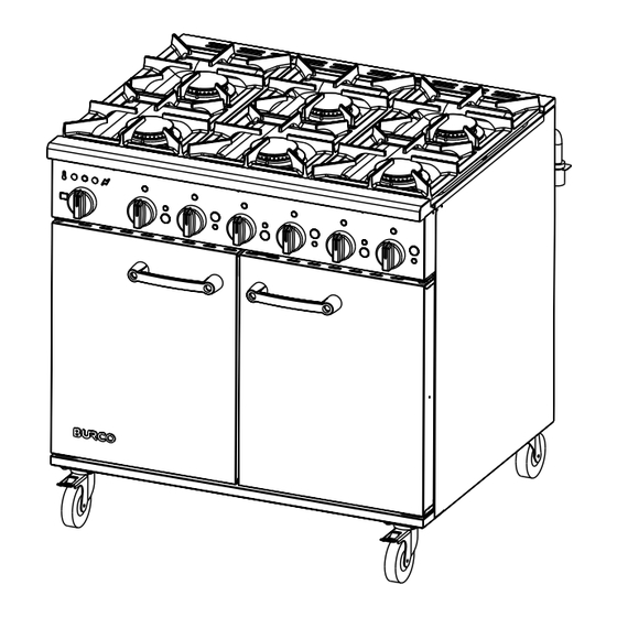
These instructions cover the Burco Titan Dual Fuel 6 Burner Commercial Catering Range
RG90DF/NG, RG90DF/LP, SKU's 444440350, 444440414
RG90DF/NG, RG90DF/LP
SKU's 444440350, 444440414
www.burco.co.uk
T I T A N
Please read and
keep these
instructions
Glen Dimplex Professional Appliances
Stoney Lane, Prescot, Merseyside, L35 2XW
Tel: 0844 815 3755
Advertisement
Table of Contents

Related Manuals for Burco TITAN RG90DF


Summary of Contents for Burco TITAN RG90DF
- Page 1 T I T A N Commercial Catering Range Please read and keep these instructions These instructions cover the Burco Titan Dual Fuel 6 Burner Commercial Catering Range RG90DF/NG, RG90DF/LP, SKU’s 444440350, 444440414 RG90DF/NG, RG90DF/LP SKU’s 444440350, 444440414 Glen Dimplex Professional Appliances...
- Page 2 INTRODUCTION This appliance must be installed by a competent person in compliance with the installation and servicing instructions and national regulations in force at the time. Particular attention must be paid to the following: Gas Safety (Installation & Use) Regulations. Health and Safety at Work etc Act.
- Page 3 TO INSTALLATION, ESPECIALLY IN DAMP CONDITIONS, THE INSULATION RESISTANCE OF THE ELEMENTS MAY FALL TO AN UNACCEPTABLE LEVEL. (I.E. BELOW 2 MEGOHM). SHOULD THIS OCCUR, IT IS RECOMMENDED THAT THE ELEMENTS BE SWITCHED ON FOR AN HOUR, THEN ALLOWED TO COOL. THIS PROCESS BEING REPEATED AS NECESSARY TO RESTORE THE REQUIRED INSULATION RESISTANCE.
-
Page 4: Gas Supply
INSTALLATION AND SERVICE GUIDE IT IS MOST IMPORTANT THAT THESE INSTRUCTIONS BE CONSULTED BEFORE INSTALLING AND COMMISSIONING THIS APPLIANCE. FAILURE TO COMPLY WITH THE SPECIFIED PROCEDURES MAY RESULT IN DAMAGE OR THE NEED FOR A SERVICE CALL. PREVENTATIVE MAINTENANCE CONTRACT In order to obtain maximum performance from this unit we would recommend that a Maintenance Contract be arranged. -
Page 5: Electrical Supply
the national requirements in force and shall be periodically examined and replaced as necessary. The installation must be tested for gas tightness. Details of this procedure can be found in IGE/UP/1. 1.4 ELECTRICAL SUPPLY This appliance is suitable for AC supplies only. The standard unit terminal arrangement is for use on a two phase supply (with neutral), terminal block 1. -
Page 6: Connection To Gas Supply
Connect a manometer and check that supply pressure is correct when the oven burner is ignited and then turned to the highest temperature setting. 1.8 BURNER ADJUSTMENT - NATURAL AND PROPANE GAS Hotplate and oven burners are fitted with fixed bypass screws and set aeration apertures, NO ADJUSTMENT is possible. -
Page 7: Instruction To User
2.4.3 Lighting sequence Important: Prior to operation, ensure ALL packing material has been removed from appliance. Hotplate 1. Ensure mains gas is turned on. 2. To light hotplate burners, press knob and turn to full flame position. Ignite burners using taper or match. Hold in knob for 5 - 10 seconds and then release. Check burner remains lit and turn knob to required position. - Page 8 3.1.5 Cleaning Burners should be cleaned periodically to maintain maximum performance. Open top burners should be cleaned as detailed in User Instructions. 3.2 INJECTORS 3.2.1 Hotplate 1. Remove burner caps and skirts. 2. Undo and carefully remove injector. 3. Replace in reverse order. 3.3 THERMOCOUPLES AND FLAME FAILURE DEVICE (FFD) 3.3.1 Hotplate flame failure device magnet unit 1.
-
Page 9: Fault Check List
3.8 RELAYS 1. Remove cover plate from rear terminal box. 2. Undo electrical connections from relay and remove fixings. 3. Replace in reverse order. Electrical connections to be restored as detailed in wiring diagram. 3.9 CONTROL FUSE The control fuse is located within rear terminal box. 3.10 THERMAL CUTOUT A thermal cutout is fitted to oven chamber back panel. -
Page 10: Section 1 - About Your Appliance
USER’S GUIDE SECTION 1 - ABOUT YOUR APPLIANCE All models are fitted with flame failure devices to shut off gas supply to burners if flames are extinguished. The oven is thermostatically controlled. All taps are the safety type with fixed HIGH and LOW settings. Hotplate controls Control knob markings are as indicated below. -
Page 11: Section 3 - Cooking Hints
IMPORTANT INFORMATION PLEASE READ THE FOLLOWING VERY CAREFULLY..AVOID MIS-USE! (MIS-USE OF THIS PRODUCT CAN BE HARMFUL). Guidance Rules for the SAFE USE of a gastronome pan on the hotplate, Size 2/1 or 1/1 gastronome pans. • Whenever two or more hotplate burners are operated below a gastronome pan, the heat input of each burner should be reduced. -
Page 12: Section 4 - Cleaning And Maintenance
SECTION 4 - CLEANING AND MAINTENANCE All surfaces are easier to clean if spillages are removed before they become burnt on and if units are cleaned daily. Stainless steel surfaces These surfaces should be cleaned with hot water and detergent then dried and polished with a soft cloth. - Page 13 Oven Clean while oven is warm but not hot. The enamelled base plate lifts out. The shelf guides can be removed by removing the four fixings. The oven base is removed by lifting at the front, and pulling towards you. GUARANTEE This appliance is guaranteed against defective materials or faulty workmanship, for a period of 12 months on labour and 36 months on parts.
- Page 14 TITAN DUAL FUEL WIRING DIAGRAM Wiring colour code: Bk - Black, Bn - Brown, Bu - Blue, Gn/Y - Green/Yellow, Or - Orange, W - White, Y - Yellow. TRAY EARTH POWER POINT INDICATOR GREEN HEATING INDICATOR T’STAT AMBER OPERATING RELAY SELECTOR 2A FUSE...
-
Page 15: Spares List
SPARES LIST Part Number Description 082982600 Burner cap assembly 082982500 Burner skirt 532991800 Oven door outer left hand side 532991900 Oven door outer right hand side 502991600 Door oven inner panel 503058100 Facia panel 082983500 Handle door 012980500 Hotplate assembly 082983800 Control knob (hotplate) 082983802... - Page 16 Customer helpline For spares and after-sales service please contact Burco on: T: 0844 815 3755 F: 0844 815 3748 info@gdha.com Glen Dimplex Professional Appliances (A Division of Glen Dimplex Home Appliances) Stoney Lane, Prescot, Merseyside L35 2XW www.burco.co.uk 082758302 © 07.2011...
Need help?
Do you have a question about the TITAN RG90DF and is the answer not in the manual?
Questions and answers