Table of Contents
Advertisement
UNVENTED (VENT-FREE) GAS LOG HEATER
OWNER'S OPERATION AND INSTALLATION MANUAL
REMOTE CONTROL READY BURNER SYSTEM MODELS
FOR USE WITH LVD18-GO, LVD24-GO, LVD18-PP, LVD24-PP,
LVD18-CH AND LVD24-CH LOG SETS
Also Design-Certified As Vented Decorative Appliances
WARNING: If the information in this manual is not
followed exactly, a fire or explosion may result causing
property damage, personal injury or loss of life.
— Do not store or use gasoline or other flammable
vapors and liquids in the vicinity of this or any other
appliance.
— WHAT TO DO IF YOU SMELL GAS
• Do not try to light any appliance.
• Do not touch any electrical switch; do not use any
phone in your building.
• Immediately call your gas supplier from a neighbor's
phone. Follow the gas supplier's instructions.
• If you cannot reach your gas supplier, call the fire
department.
— Installation and service must be performed by a quali-
fied installer, service agency or the gas supplier.
INSTALLER: Leave this manual with the appliance.
CONSUMER: Retain this manual for future reference.
For more information, visit www.fmiproducts.com
VD1824NR AND VD1824PR
PFS
®
US
Advertisement
Table of Contents

Related Manuals for Vantage Hearth Vantage Hearth

Summary of Contents for Vantage Hearth Vantage Hearth
- Page 1 UNVENTED (VENT-FREE) GAS LOG HEATER OWNER’S OPERATION AND INSTALLATION MANUAL ® REMOTE CONTROL READY BURNER SYSTEM MODELS VD1824NR AND VD1824PR FOR USE WITH LVD18-GO, LVD24-GO, LVD18-PP, LVD24-PP, LVD18-CH AND LVD24-CH LOG SETS Also Design-Certified As Vented Decorative Appliances WARNING: If the information in this manual is not followed exactly, a fire or explosion may result causing property damage, personal injury or loss of life.
-
Page 2: Table Of Contents
TABLE OF CONTENTS Safety ..............2 Cleaning and Maintenance ........ 22 Local Codes............5 Troubleshooting ..........24 Product Identification ........... 5 Parts ..............28 Optional Remote Control Accessories ....5 Specifications ............ 33 Unpacking............5 Service Hints ............. 33 Product Features ..........5 Technical Service.......... - Page 3 SAFETY Continued WARNING: This product con- WARNING: Do not allow fans tains and/or generates chemicals to blow directly into the fireplace. known to the state of California Avoid any drafts that alter burner to cause cancer or birth defects flame patterns. Ceiling fans can or other reproductive harm.
- Page 4 SAFETY Continued 1. This appliance is only for use with the type 9. Before using furniture polish, wax, carpet cleaner or similar products, turn heater off. If of gas indicated on the rating plate. This heated, the vapors from these products may appliance is not convertible for use with create a white powder residue within burner other gases.
-
Page 5: Local Codes
3. Check heater for any shipping damage. If PIEZO IGNITION SYSTEM heater is damaged call FMI PRODUCTS, This heater has a piezo ignitor. This system re- LLC at 1-866-328-4537 for replacement quires no matches, batteries or other sources parts before returning to dealer. -
Page 6: Air For Combustion And Ventilation
AIR FOR COMBUSTION AND VENTILATION Unusually tight construction is defined as WARNING: This heater shall construction where: not be installed in a room or space a. walls and ceilings exposed to the out- unless the required volume of side atmosphere have a continuous indoor combustion air is provided water vapor retarder with a rating of one perm (6 x 10... - Page 7 AIR FOR COMBUSTION AND VENTILATION Continued 1. Determine the volume of the space (length B. Vent room directly to the outdoors. See x width x height). Ventilation Air From Outdoors, page 8. Length x Width x Height =__________cu. ft. C. Install a lower Btu/Hr fireplace, if lower Btu/ (volume of space) Hr size makes room unconfined.
-
Page 8: Installation
AIR FOR COMBUSTION AND VENTILATION Continued Ventilation Air From Outdoors Provide extra fresh air by using ventilation Ventilated Outlet Attic grills or ducts. You must provide two perma- nent openings: one within 12" of the ceiling Outlet and one within 12" of the floor. Connect these To Attic items directly to the outdoors or spaces open to the outdoors. - Page 9 INSTALLATION Continued WARNING: Never install the WARNING: Maintain the heater minimum clearances. If you can, • in a bedroom or bathroom provide greater clearances from unless installed as a vented floor, ceiling and adjoining wall. appliance, see page 11 Carefully follow these instructions. This will •...
-
Page 10: Mantel Clearances
INSTALLATION Continued Minimum Noncombustible Material If Using Mantel Clearances If Not Using Mantel You must have noncombustible material(s) Note: If using a mantel proceed to If Using above the fireplace opening. Noncombustible materials (such as slate, marble, tile, etc.) must Mantel. - Page 11 INSTALLATION Continued FLOOR CLEARANCES Determining Minimum Mantel Clearance When Using a Hood A. If installing appliance on the floor level, If minimum clearances in Figure 6, page 10, are you must maintain the minimum distance not met, you must have a hood. When using of 14"...
- Page 12 INSTALLATION Continued If reasons number 1 or 2 apply to you, WARNING: If installing in a you must permanently open chimney flue damper. You must install the damper clamp sunken fireplace, special care accessory (to order, see Accessories, page is needed. You must raise the 34).
- Page 13 INSTALLATION Continued CAUTION: Never connect Flexible Gas propane/LP fireplace directly Hose (if allowed to the propane/LP supply. This by local codes) heater requires an external regu- Fitting lator (not supplied). Install the external regulator between the heater and propane/LP supply. Figure 11 - Attaching Flexible Gas Hose Installation Items Needed to Heater...
- Page 14 INSTALLATION Continued PROPANE/LP WARNING: Never connect From External Equipment Shutoff Regulator (11" natural gas fireplace to private Valve With 1/8" W.C.** to 14" W.C. NPT Tap* (non-utility) gas wells. This gas Pressure) is commonly known as wellhead NATURAL Approved gas. From Gas Meter Flexible (5"...
- Page 15 INSTALLATION Continued 3. Make sure control knob of heater is in the CAUTION: Make sure exter- OFF position. nal regulator has been installed 4. Check all joints from equipment shutoff between propane/LP supply valve to gas control (see Figures 16 and 17).
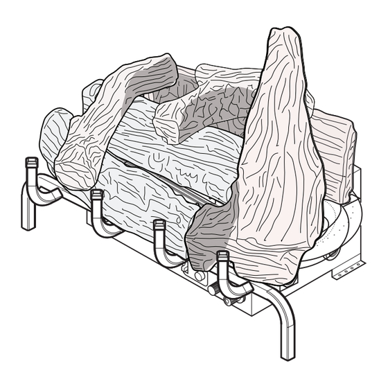
- Page 16 INSTALLATION Continued INSTALLING LOGS 3. Place front log onto grate as shown in Figure 19. Front log has cut outs for the WARNING: Failure to position fingers of the grate to fit into. the parts in accordance with these diagrams or failure to use only parts specifically approved with Front Log this heater may result in property...
- Page 17 INSTALLATION Continued Center Front Log Right Crossover Crossover Left Crossover Square Peg on Middle Square Peg on Rear Log Round Peg on Front Log Round Peg Grate on Center Figure 20 - Installing Left, Center and Figure 22 - Installing Front Log Right Crossover Logs LVD18-PP AND LVD24-PP 4.
- Page 18 INSTALLATION Continued LVD18-CH AND LVD24-CH 3. Place the front log onto grate as shown in Figure 26. It is very important to install these logs exactly as instructed. Do not modify logs. Only use Middle Log logs supplied with heater. 1.
- Page 19 INSTALLATION Continued 5. Place the top middle log onto the rear 7. Final assembly is shown in Figure 30. & middle logs as shown in Figure 28. Make sure to match up the shape on the bottom of the top middle log with the notches in the rear and middle logs.
-
Page 20: Operation
OPERATION FOR YOUR SAFETY LIGHTING READ BEFORE LIGHTING INSTRUCTIONS WARNING: If you do not fol- WARNING: low these instructions exactly, • If fireplace has glass doors, a fire or explosion may result never operate this heater with causing property damage, per- glass doors closed. - Page 21 OPERATION Continued 4. Press in and turn control knob clockwise 11. Set flame adjustment knob to any level to the OFF position (see Figure 31). between HI and LO. 5. Wait five (5) minutes to clear out any gas. 12. To leave pilot lit and shut off burners only: Then smell for gas, including near the turn control knob clockwise to the...
-
Page 22: Inspecting Burners
INSPECTING BURNERS Thermocouple Check pilot flame pattern and burner flame Pilot Burner patterns often. PILOT FLAME PATTERN Figure 34 shows a correct pilot flame pattern. Figure 35 shows an incorrect pilot flame pat- Figure 34 - Correct Pilot Flame Pattern tern. - Page 23 CLEANING AND MAINTENANCE Continued 1. Shut off the unit, including the pilot. Allow Ports/Slots the unit to cool for at least thirty minutes. 2. Inspect burner, pilot and primary air inlet holes on Orifice holder for dust and dirt Burner Tube (see Figures 36 and 37).
-
Page 24: Troubleshooting
TROUBLESHOOTING WARNING: Turn off heater and let cool before servicing. Only a qualified service person should service and repair heater. CAUTION: Never use a wire, needle or similar object to clean ODS/pilot. This can damage ODS/pilot unit. Note: All troubleshooting items are listed in order of operation. OBSERVED PROBLEM POSSIBLE CAUSE REMEDY... - Page 25 TROUBLESHOOTING Continued OBSERVED PROBLEM POSSIBLE CAUSE REMEDY ODS/pilot lights but flame 1. Control knob not fully 1. Press in control knob fully goes out when control knob pressed in is released 2. Control knob not pressed in 2. After ODS/pilot lights, keep long enough control knob pressed in 30 seconds...
- Page 26 TROUBLESHOOTING Continued OBSERVED PROBLEM POSSIBLE CAUSE REMEDY Slight smoke or odor during 1. Not enough air 1. Check burner for dirt and initial operation debris. If found, clean burner (see Cleaning and Maintenance, page 22) 2. Gas regulator defective 2. Replace gas control 3.
- Page 27 TROUBLESHOOTING Continued WARNING: If you smell gas • Shut off gas supply. • Do not try to light any appliance. • Do not touch any electrical switch; do not use any phone in your building. • Immediately call your gas supplier from a neighbor’s phone. Fol- low the gas supplier’s instructions.
-
Page 28: Parts
PARTS BURNER SYSTEMS VD1824NR AND VD1824PR www.fmiproducts.com 125502-01D... - Page 29 PARTS This list contains replaceable parts used in your heater. When ordering parts, follow the instructions listed under Replacement Parts on page 33 of this manual. NO. PART NO. DESCRIPTION QTY. M11084-26 Screw, HWH AB 10-16 x .38 • • M12461-26 Screw, HX SLT WSR 10-32 x .38 •...
- Page 30 PARTS LVD18-GO AND LVD24-GO LOGS NO. PART NO. DESCRIPTION QTY. 124673-01 Front Log • 124674-01 Front Log • 124673-02 Center Log • 124674-02 Center Log • 124673-03 Rear Log • 124674-03 Rear Log • 124673-04 Left Crossover Log • 124674-04 Left Crossover Log •...
- Page 31 PARTS LVD18-PP AND LVD24-PP LOGS NO. PART NO. DESCRIPTION QTY. 123190-01 Rear Log • 123190-06 Rear Log • 123190-02 Middle Log • 123190-07 Center Log • 123190-03 Front Log • 123190-08 Front Log • 123190-04 Top Right Log • 123190-09 Top Right Log •...
- Page 32 PARTS LVD18-CH AND LVD24-CH LOGS PART NUMBERS DESCRIPTION LVD18-CH LVD24-CH 125959-04 125959-05 Rear Log (#1) 125959-03 125959-03 Middle Log (#2) 125959-01 125959-02 Front Log (#3) 125959-08 125959-08 Top Right Log (#4) 125959-07 125959-07 Top Middle Log (#5) 125959-06 125959-06 Top Left Log (#6) www.fmiproducts.com 125502-01D...
-
Page 33: Specifications
You may have further questions about • pilot will not stay lit installation, operation or troubleshooting. If so, contact FMI PRODUCTS, LLC at • burners will have delayed ignition 1-866-328-4537. When calling please have • heater will not produce specified heat your model and serial numbers of your heater •... -
Page 34: Accessories
ROOM TEMP Purchase these accessories from your local dealer. If they can not supply these accessories, call FMI PRODUCTS, LLC at 1-866-328-4537 MODE for referral information. You can also write to the address listed on the back page of this manual. - Page 35 NOTES _____________________________________________________ ______________________________________________________ ______________________________________________________ ______________________________________________________ ______________________________________________________ ______________________________________________________ ______________________________________________________ ______________________________________________________ ______________________________________________________ ______________________________________________________ ______________________________________________________ ______________________________________________________ ______________________________________________________ _____________________________________________________ ______________________________________________________ ______________________________________________________ ______________________________________________________ ______________________________________________________ ______________________________________________________ ______________________________________________________ ______________________________________________________ ______________________________________________________ ______________________________________________________ ______________________________________________________ ______________________________________________________ ______________________________________________________ _____________________________________________________ ______________________________________________________ ______________________________________________________ ______________________________________________________ ______________________________________________________ ______________________________________________________ ______________________________________________________ ______________________________________________________ ______________________________________________________ www.fmiproducts.com 125502-01D...
-
Page 36: Warranty
FMI PRODUCTS, LLC’s liability is limited to the purchase price of the product, and FMI PRODUCTS, LLC shall not be liable for any other damages whatsoever under any circumstances including indirect, incidental, or consequential damages.
Need help?
Do you have a question about the Vantage Hearth and is the answer not in the manual?
Questions and answers