Table of Contents
Advertisement
2013
Confidential
Page 1
8/23/20132--
'
'
O
w
n
e
r
s
M
a
n
u
a
l
O
w
n
e
r
s
M
a
n
u
a
l
40 and 50 Horsepower
Two stroke Low pressure Direct
Injection (TLDI)
Multi-Fuel SubmersibleOutboard Motor
This manual has been prepared for the United States Guardian Angels for
service of the Multi-fuel, Submersible Outboard motor designed and manufactured
under Contract No. N61331•11•C-0008, dated 3/4/11. The data presented in this
manual was revised as of August 2013 representing the latest revision.
Advertisement
Table of Contents

Related Manuals for Raider Outboard Motor


Summary of Contents for Raider Outboard Motor
- Page 1 Multi-Fuel SubmersibleOutboard Motor This manual has been prepared for the United States Guardian Angels for service of the Multi-fuel, Submersible Outboard motor designed and manufactured under Contract No. N61331•11•C-0008, dated 3/4/11. The data presented in this manual was revised as of August 2013 representing the latest revision.
-
Page 2: Table Of Contents
Dewater Procedure ......................16 v. Post Submersion Procedure ....................17 4. General Maintenance_______________________________________________ a. Fuel/Oil Requirements .......................18 b. Removing and Carrying the Raider ..................19 c. Tool Kit and spare parts .....................20 d. Corrosion Protection ......................20 e. Optional Accessories ......................20 f. Trouble shooting .........................21 g. -
Page 3: Your Raider Outboard Motor
The serial number is engraved on the side of the transom mount. c. Safety/Danger/Warnings/Cautions Before operating the Raider outboard motor, be sure to thoroughly read and understand this Users manual and follow all of the instructions shown. Of particular importance in- formation preceded by the words or symbols draw attention to safety issues. - Page 4 It offers superior human factors design for the operator. It is lighter than any outboard motor in its class.
-
Page 5: Specifications Table
Specifications Table ITEM RAIDER 50 HP TLDI Overall length 1120 mm (44.1 in.) Overall width 384 mm (15.1 in.) Overall height 1514 mm (59.6 in.) 92.0 kg (202 lbs.) – w/o composites Weight Transom length 530 mm (20.9 in.) -
Page 6: Tldi Verses Carburetor
f. TLDI verses Carburetor TLDI is an abbreviation that stands for Two-stroke Low-pressure Direct Injection. The air assisted, low-pressure direct injection system has been combined with the in- ducted ignition system and the Engine Control Unit, which performs control or fuel mix- ture, injection timing and ignition timing to maximize combustion efficiency in the TLDI engine. -
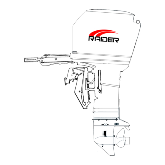
Page 7: Tldi Raider Parts Identification
TLDI RAIDER Parts Identification RAIDER A Rear dewatering valve B Front dewatering valve C Mid dewatering valve... -
Page 8: Raider Installation
Installation of single Engine The Raider has been designed to be released from submarines and air dropped. This in- stallation will discuss a typical installation – no special operations installation. Position the outboard engine at the exact center of the stern and mount it against the Rub- ber Inflatable Boat pad or plate. -
Page 9: Installation Of Twin Engines
The Raider has been designed to have the anti-ventilation plate at a level 10 to 30 mm (0.4 to 1.2 inches) below the bottom of the boat as shown above. Be sure the anti-ventilation plate of the Rader outboard is below the water surface when running with wide open throttle. -
Page 10: Propeller
Propeller A propeller must be selected so that the engine rpm measured at wide open throttle while cruising is within the maximum operating range. In the Raider that range is between 5150 and 5850 rpm. To ensure optimum performance, the propeller should match the boat type and its load.... -
Page 11: Raider Running
Raider Break in 10 Hours. The Raider has provided the break in at the factory. The most critical time in the life of the Raider engine is the first 10 hours of operation. Correct operation during this break-in period will pro- long the life of the engine and ensure optimum performance. -
Page 12: After Raider Starts/Warm Up
When the engine is new or has been left without operation for a long time execute the following operation for forcedly feeding the engine oil to the oil line before starting the Raider Engine. 1. Disconnect the link rod by turning the rod snap interlocking with the oil pump as shown in the figure. -
Page 13: Throttle Friction
g. Throttle Friction To increase throttle friction, turn the throttle friction screw clock- wise. To decrease friction, turn the throttle friction screw counter- clockwise. DO NOT over tighten. h. Shifting To avoid gear case damage: DO NOT attempt to shift engine from NEUTRAL to FORWARD or REVERSE when the engine is NOT running. -
Page 14: Stopping Raider
Place the engine in the normal vertical position. For additional road clearance, move angle adjusting rod to an outer stern bracket position. Refer to Raider Trim Angle. DO NOT use the tilt support as a Trailering bracket. The engine should always be resting on the angle adjusting stop rod when under full power or when trailering. -
Page 15: Trim Tab Adjustment
m. Trim Tab Adjustment n. Shallow Water Drive The engines shallow water tilt is controlled by the gas assist tilt cylinder Engage Shallow Water Drive 1. Move red button tilt/run lever to TILT position 2. Raise the engine to the desired shallow drive position. 3. -
Page 16: Impact Damage
The engine’s Water Temperature sensor is NOT a warning device. The Raider does not have an overheat warning. The Raider will not initiate a warning to prevent powerhead damage. The EMM will only monitor and store a code in the event of an overheat. -
Page 17: Emergency Starting
If you suspect the engine is overheating or has overheated, STOP the engine only when it is safe. When operating the engine, the water intakes must be completely submerged. Make sure the water intake screens are not in- stalled upside down (ramps must be forward). If upside down, the engine will overheat. -
Page 18: Pre-Submersion Procedure
1. Make sure the inside of all electrical connectors are thoroughly connected. 2. Insure the de-watering valves at the back, mid and front of the Raider is working correctly by turning valves to closed position. 3. Any time the ECU or other connectors are removed, insure they are re-connected correctly. -
Page 19: Post Submersion Procedure
If the RAIDER is re-submersed after your mission and it cannot be serviced, keep it submersed to avoid prolonged exposure to the atmosphere, until it can be serviced. If the Raider is brought on deck and it can’t be operated or serviced, keep it submerse in fresh water, but get it prepared for your next mission as soon as possible. -
Page 20: General Maintenance
General Safety Warnings When replacement parts are required, use genuine Raider parts or parts with equivalent characteristics including type, strength, and materi- al. Failure to do so may result in product malfunction and possible injury to the operator and/or passengers. -
Page 21: Removing And Carrying The Raider
Removing and Carrying the Raider... -
Page 22: Tool Kit And Spare Parts
Optional Accessories 1) Both the 50 and 40 Horsepower can be purchased with a battery system that is enclosed under the cowling. This battery is safe underwater; can be recharged by the Raider motor once the motor is started. -
Page 23: Trouble Shooting
4. If the engine is removed from the boat, examine all hardware you loosened or removed. Re- place damaged or missing parts with genuine Raiderparts or equivalent. These fasteners are made of special materials to resist weakening and rusting. Do not substitute these fasteners with nuts and bolts which look the same. -
Page 24: Out Of Storage Service
5. Inspect the engine's steering, throttle, de-watering and shift systems for damage due to corrosion, aging, lack of maintenance, or abuse. Follow the maintenance and lubrication recommendations when servicing these systems. 6. Replace the engine's fuel filter. 7. Clean and inspect oil reservoir. Fill the oil tank with recommended oil to reduce or prevent con- densation from forming in the tank during storage. -
Page 25: After Submersion
After Submersion After submersion or after a mission, the Raider must be prepared to be returned to nonuse or prepared for your next mission. If the Raider is re-submersed after your mission and it cannot be serviced, keep it sub- mersed until it can be serviced to avoid prolonged exposure to the atmosphere. - Page 26 Motor on Stand Back of Raider Front of Raider Top view of rear dewatering valve...
- Page 27 Rugged o Durable Originally designed for Japanese fisherman to work day in and day out World-wide parts availability results in life cycle cost savings Most parts for the Raider 50 are common to the Raider 40...
- Page 28 Robotics and Conceptual Engineering, Inc. 2702 Lake Dauterive Rd. Loreauville, LA 70552 (337) 577-6810 7887 Bryan Dairy Rd Largo, FL 33777 (321) 403-3585 August 2013...
Need help?
Do you have a question about the Outboard Motor and is the answer not in the manual?
Questions and answers