Table of Contents
Advertisement
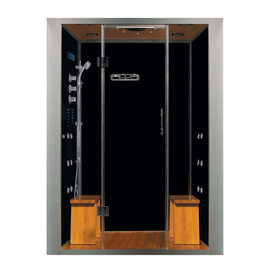
WS-112
Installation & Operations Manual
Note: You must read all installation & operation instructions prior to assembly and use of this unit.
1 |
P a g e
Rev 3/2012
Advertisement
Table of Contents

Subscribe to Our Youtube Channel
Related Manuals for Steam Planet WS-112

Summary of Contents for Steam Planet WS-112
- Page 1 WS-112 Installation & Operations Manual Note: You must read all installation & operation instructions prior to assembly and use of this unit. P a g e Rev 3/2012...
- Page 2 Table of Contents Part 1 Installation Manual …………………………………………… 3 – 15 Cleaning & Maintenance …………………………………………… Part 2 S6 Operations Manual a. Safety Notes …………………………………………… b. Parameter for Steam Cabin …………………………. c. Control Box Electrical Diagram ………………… d. S6 Wiring Diagram ………………………..…………...
- Page 3 Part 1 Electric Parameter Size Model System Voltage Power Frequency Length Width Height WS112(32) Steam System 220V 60-50Hz 59 Inch 32 Inch 84.5 Inch WS112(36) Steam System 200V 60-50Hz 59 Inch 36 Inch 84.5 Inch WS112(40) Steam System 200V 60-50Hz 59Inch 40 Inch 84.5 Inch...
- Page 4 P a g e Rev 3/2012...
- Page 5 Tools required for installation: Leveler Screw driver Silicone Spanner Electric Drill Triangle Ruler Hammer P a g e Rev 3/2012...
- Page 6 Place of Installation The distance between Wall A and Wall B should be within 1510 to 1530mm (59.5 to 60.3 inches). The distance between Wall A and Wall B bottom to 2000mm (78.75inches) height should be less than 10mm (.4inches). 1510mm to 1530mm = 59.5”...
- Page 7 Door Frame Installation Drill holes on Wall A and B, use the inflating nut. i. Note: For California: Get the door frame fixed to wall with tapping screws and blocks 820mm = 32.3in P a g e Rev 3/2012...
- Page 8 Installing Shower Walls Get Power supply and water supply connected Attach all the panels with taping screws P a g e Rev 3/2012...
- Page 9 Attach All Side Panels to the Floor (not with custom stone base) Drill hose on the floor (or optional acrylic base) Attach all sides with tapping screws and blocks P a g e Rev 3/2012...
- Page 10 Apply silicone to seal the gap between panels and floor. Leave the corners without silicone. 10 | P a g e Rev 3/2012...
- Page 11 Install the front fixed glass 11 | P a g e Rev 3/2012...
- Page 12 Install the glass door with hinges. 12 | P a g e Rev 3/2012...
- Page 13 Install the door handle & adjustable handheld shower bar 13 | P a g e Rev 3/2012...
- Page 14 Installing the ceiling Connect the power and water supply to the wooden ceiling Install the ceiling with tapping screws and down the decoration cap 14 | P a g e Rev 3/2012...
- Page 15 Install the aluminum trim 15 | P a g e Rev 3/2012...
- Page 16 Once all is connected, place the wooden shower grid floors and benches inside the unit. Please, do not use the unit for at least 24hours or until the silicone is completely dried. 16 | P a g e Rev 3/2012...
- Page 17 Cleaning 1. Daily cleaning will be much easier if you squidgy the surface frequently. You may use Windex and a soft cloth; never use the detergents with acetone and ammonia content. Never use any abrasive, gritty cleaning or scouring materials. 2.
- Page 18 Part 2 Safety Notes: 1. The power supply must be installed according to the local standard and with GFCI (Ground Fault Current Interrupter). Test the GFCI before using to confirm its security and validity 2. The ground for electrical appliances should be connected to fixed earth wire forever. 3.
- Page 19 Electrical Diagram for Control Box: 19 | P a g e Rev 3/2012...
- Page 20 S6 Wiring Diagram 20 | P a g e Rev 3/2012...
- Page 21 Parts Information: LCD Display Fahrenheit Degree Celsius Degree Temperature Temperature Indicator Time Setting FM Radio Frequency FM Radio Volume FM Radio Channel Chromatherapy on/off 10. Ventilator on/off 11. Steam on/off 12. Power on Indicator 13. FM Radio Frequency 14. Mp3 on/off Control Panel for Steam Cabin: 21 | P a g e...
- Page 22 Control Parts Information for Steam Cabin: Steam Temperature Sensor LCD Display Control Panel Water Diverter Water Flow Adjustment Water Temperature Adjustment Back Massage Jet Steam Outlet Handheld Shower Set Steam Generator Cleaning Liquid Inlet 22 | P a g e Rev 3/2012...
- Page 23 Power on/off Push any button to light the display, and press the power on/off switch to start the system, as shown by Picture 2. Push the power on/off switch again to turn off the system and display. The drain valve for the steam generator stays open for one minute.
- Page 24 Chromatherapy This button controls the color of the Chromatherapy lamps (picture 5). When the Chromatherapy function starts, the lamp symbol display twinklesflashes. Ventilator This button turns ventilation on/off. When ventilation is turned on, the ventilation symbol on the LCD display twinkles.
- Page 25 First, choose a radio frequency as the MP3 channel. Please note that the radio frequency chosen should have no radio station to prevent interruption. Set the same frequency on the LCD as the one on the MP3 emitter. Start the MP3 function. ...
- Page 26 Channel Memory Channel Memory Setting: Start FM Radio Set serial number push button and picture 14 shows on display push button again, fissure from 1 to 8 shows circularly; stop pushing this button when the wanted fissure shows. ...
- Page 27 27 | P a g e Rev 3/2012...
- Page 28 Steam Generator Cleaning Remove the cover of the cleaning liquid inlet and input around 1L of citric or acetic acid. Start the steam function to fill the steam generator with water. Stop the steam function before the steam starts to come out (acid steam is detrimental to plated parts.
- Page 29 29 | P a g e Rev 3/2012...
Need help?
Do you have a question about the WS-112 and is the answer not in the manual?
Questions and answers