Table of Contents
Advertisement
Q7C3 LCD Monitor Service Guide
Table of Contents
...................................................................................................................................4
2.1 Environment.................................................................................................................................4
............................................................................................................................................................. 4
2.2 Transportation .............................................................................................................................5
2.3 Packing Configuration ................................................................................................................6
2.4 Electrostatic Discharge Requirements.......................................................................................8
2.5 Safety Requirements....................................................................................................................8
2.6 EMI Requirements ......................................................................................................................8
2.7 Reliability......................................................................................................................................9
2.8 Mechanical Design for TCO 03: .................................................................................................9
2.9 Environment Protection Design: ................................................................................................9
2.10 Acoustical Noise .........................................................................................................................9
3.1 Input Signal Requirements .........................................................................................................9
3.2 Function ........................................................................................................................................11
3.3 Number of display colors: ...........................................................................................................12
3.4 Adjustment function ....................................................................................................................12
3.5 Power Supply Requirements.......................................................................................................12
..........................................................................................................4
..................................................................................................................................................... 4
........................................................................................................................................... 4
..................................................................................................................................... 6
.................................................................................................................................. 6
....................................................................................................................................... 7
......................................................................................................................................... 8
......................................................................................................................... 8
.................................................................................................................................................. 10
...................................................................................................................................................... 10
................................................................................................................................................. 11
............................................................................................................................ 12
........................................................................................................................... 13
................................................................................................... 5
.......................................................................................................... 5
........................................................................................... 6
.......................................................................................9
....................................................................................................... 9
Engineering Specification
1
Advertisement
Table of Contents

Related Manuals for BenQ Q7C3


Summary of Contents for BenQ Q7C3
-
Page 1: Table Of Contents
Q7C3 LCD Monitor Service Guide Engineering Specification Table of Contents 1. Introduction ...........................4 2. Operational Specification ......................4 2.1 Environment..........................4 2.1.1 Temperature ..............................4 2.1.2 Relative Humidity ............................4 2.1.3 Altitude ................................4 2.2 Transportation ..........................5 2.2.1 Vibration Test (Package, Non-Operating) .................... - Page 2 Q7C3 LCD Monitor Service Guide Engineering Specification Table of Contents 3.5.3 Power Management ............................13 3.6 Specification of Inverter ......................13 3.7 Panel optical Characteristics ......................14 4. Functional specification ......................16 4.1 Display Quality..........................16 4.1.1 Display Data Area (with full white pattern) ....................
- Page 3 Q7C3 LCD Monitor Service Guide Engineering Specification Table of Contents 6.3.2 Outside Cabinet, access to the following elements ..................18 6.3.3 Cover Removal, Access ..........................18 6.4 Equipment & Tools Required.....................18 6.4.1 Standard Test Equipment ..........................18 6.4.2 Documentation ..............................18 6.5 Electrical Emission and Energy Saving summary for TCO 03 ..........18...
-
Page 4: Introduction
Q7C3 LCD Monitor Service Guide Engineering Specification 1. Introduction This specification describes a 17.0” color TFT LCD monitor which is supported by analog interface solution and support maximum resolution 1280x1024 at 76 Hz refresh rate. It has the following features: - User controls: (a) “Power on/off”... -
Page 5: Transportation
Q7C3 LCD Monitor Service Guide Engineering Specification 2.2 Transportation 2.2.1 Vibration Test (Package, Non-Operating) A) Sine-wave vibration for initial resonance sweeps and dwell * Sine sweep Frequency (Hz) Status 5 ~ 26.6 0.6G 26.6 ~ 50 0.016" 50 ~ 500 1.5G... -
Page 6: Vibration Test (Unpackaged, Non-Operating)
Q7C3 LCD Monitor Service Guide Engineering Specification B) Drop Sequence 1. Top Surface 2. Front 3. Bottom Manufacturing 4. Rear joint 5. Right 6. Left -Corner 5-3-2 select at weakness side [the low left(or right) corner of the front panel]... -
Page 7: Carton Specification
Q7C3 LCD Monitor Service Guide Engineering Specification 20'*8'*8'6 Container Type 40'*8'*8'6" Steel 40'*8'*9'6" " Steel High Cube Steel Gross 24,000 30,480 30,480 Weight (Kegs) Tare 2,370 4,000 4,200 Payload 21,630 26,480 26,280 Length 5,898 12,031 12,031 Interior Measurement (mm) Width... -
Page 8: Pallet Specification
Q7C3 LCD Monitor Service Guide Engineering Specification 2.3.3 Pallet Specification a. Dimension Transport Type Pallet A Pallet B Pallet C Pallet D Length Shipping Pallet 1254 Width 1254 Dimension (mm) Height Length Air Transport Pallet Width Dimension (mm) Height 2.3.4 Container Carrying Capacity a. -
Page 9: Reliability
Q7C3 LCD Monitor Service Guide Engineering Specification -DNSF compliance...EN55022, Class B. -MPR2 compliance - TCO99 -C-Tick -BSMI -EPA 2. The sample for EMI agency approval should be under 4 dB of the limit. The production pilot run units should be under 3 dB of the limit. -
Page 10: Video Signals
Q7C3 LCD Monitor Service Guide Engineering Specification 15pin D-sub female 1 RED VIDEO 2 GREEN VIDEO 3 BLUE VIDEO 4 GROUND 5 Cable Detect 6 RED GROUND 7 GREEN GROUND 8 BLUE GROUND 9 PC5V 10 SYNC GROUND 11 GROUND... -
Page 11: Function
Q7C3 LCD Monitor Service Guide Engineering Specification 3.2 Function 3.2.1 Support timing This Interface board is designed to operate in any of the following video mode. Incoming display mode (Input timing) Multi-scan operation Horizontal Vertical Dot Clock Actual display Resolution... -
Page 12: Number Of Display Colors
Q7C3 LCD Monitor Service Guide Engineering Specification Notes : (1) If the incoming display mode is not supported by this I/F board listed above, the picture can show up or doesn’t which is unpredictable, even the picture can display but probably isn’t good or clear. -
Page 13: Output Power Requirement
Q7C3 LCD Monitor Service Guide Engineering Specification 70% minimum (measuring at 115Vac and full load) Power saving mode < 1 Watts at 115vac 3.5.2 Output Power Requirement The power circuit shall supply DC power outputs as followings: Output Nominal Regulation... -
Page 14: Panel Optical Characteristics
Q7C3 LCD Monitor Service Guide Engineering Specification 3.7 Panel optical Characteristics Item Unit Conditions Min. Typ. Max. Horizontal (Right) CR = 10 (Left) Vertical (Up) CR = 10 (Down) Viewing Angle [degree] Horizontal (Right) CR = 5 (Left) Vertical (Up) - Page 15 Q7C3 LCD Monitor Service Guide Engineering Specification 4. Response time TrR measures the transition time of L1 relative luminance from white to black state, from 90% to 10% (see graph below) TrD measures the transition time of L1 relative luminance from black to white state, from 10% to 90% (see graph below)
-
Page 16: Functional Specification
Q7C3 LCD Monitor Service Guide Engineering Specification Brightness Uniformity = Min. brightness / Max. brightness x 100 % > 70% 4. Functional specification All the tests to verify specifications in this section must be performed under the following standard conditions unless otherwise noted. -
Page 17: Physical Specifications
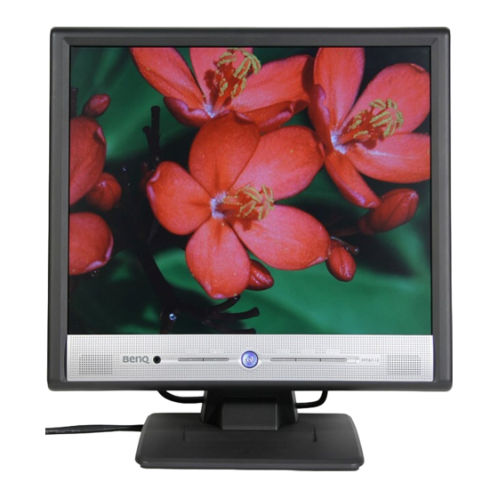
Q7C3 LCD Monitor Service Guide Engineering Specification 5. Physical Specifications 5.1 Physical Dimension & Appearance 5.1.1 Overall Dimensions: 375mm (W) X 370mm (H) X 155mm (D) 5.1.2 Outer Appearance: see Fig.1 5.2 Construction and Materials on outer surface (1) Materials: Plastic (2) Color: To be defined for Model 5.3 Base... -
Page 18: Accessibility
Q7C3 LCD Monitor Service Guide Engineering Specification 6.3 Accessibility 6.3.1 General: All panels, covers, and major assemblies are removable without disruption of permanent mounting or fasteners. 6.3.2 Outside Cabinet, access to the following elements -Operating Controls -AC Inlet -Audio in 6.3.3 Cover Removal, Access... -
Page 19: Fig. 1 Physical Dimension Front View And Side View
Q7C3 LCD Monitor Service Guide Engineering Specification Fig. 1 Physical Dimension Front View and Side view... - Page 20 BENQ LCD FP767-12 Q7C3 Spare Parts List P/N: 99.L9072.RBA/RBE ITEM DESCRIPTION PART NO. LOCATION PCBA I/F BD Q7C3-12MS AU 55.L9001.021 IC FLASH MTV312MV64 (AJ) PLCC4 71.31264.A03 IC LVDS/RSDS MVPRL-HN PQPF 160P 71.MVPRL.A0E IC EEPROM AT24C04N-10SI-2.7SON 72.02404.N01 IC CMOS 74LVC14A SO-N 14P 73.07414.061...
-
Page 21: Alignment Procedure
Q7C3 LCD Monitor Service Guide Alignment Procedure 1. Alignment procedure (for function adjustment) A. Preparation: 1. Setup input timing ICL-605, 32-Grays pattern. 2. Setup unit and keep it warm up at least 30 minutes. B. Timing adjustment: 1. Enter factory setting area (press “LEFT”, “EXIT” and then press “SOFTPOWER”). - Page 22 Q7C3 LCD Monitor Service Guide Alignment Procedure 4. Turns off the monitor power. E. Writing EDID file: 1. Setup a PC with DDC card. 2. Connect PC to monitor with a D-sub signal cable. 3. Please refer to the C212 for the correct EDID file.
- Page 23 Q7C3 LCD Monitor Service Guide Alignment Procedure F. Command definition: MCU COMMAND LIST FUNCTION BYTE1 BYTE2 BYTE3 BYTE4 Write Contrast Data checksum Write Brightness Data checksum Write Red Gain Data checksum Write Green Gain Data checksum Write Blue Gain Data...
- Page 24 Q7C3 LCD Monitor Service Guide Alignment Procedure Read User R-Gain data from NVRAM checksum Read User G-Gain data from NVRAM checksum Read User B-Gain data from NVRAM checksum Change Color Temperature to C1 checksum Change Color Temperature to C2 checksum...
- Page 25 Q7C3 LCD Monitor Service Guide Alignment Procedure 2. Dressing A. Check the two spring on the BKT B. Screws on the interface & power board...
- Page 26 Q7C3 LCD Monitor Service Guide Alignment Procedure C. Plastic fixture on the interface board D. Closing plastic on the BKT:...
- Page 27 Q7C3 LCD Monitor Service Guide Alignment Procedure E. Tapes on backlight wire F. Spring at the top of BKT:...
- Page 28 Q7C3 LCD Monitor Service Guide Alignment Procedure G. Two gaskets at the bottom of BKT H. Place D-sub cover and its screw...
- Page 29 Q7C3 LCD Monitor Service Guide Alignment Procedure I. Backlight wire J. Two screws on panel left side...
- Page 30 Q7C3 LCD Monitor Service Guide Alignment Procedure K. Two screws on panel right side L. Two FFC cables fixed on panel socket...
- Page 31 Q7C3 LCD Monitor Service Guide Alignment Procedure M. Two speakers fixed on BZL N. Spring on control board to contact panel...
- Page 32 Q7C3 LCD Monitor Service Guide Alignment Procedure O. Control board 3pin wire dressing P. Contorl board 9pin wire dressing...
- Page 33 Q7C3 LCD Monitor Service Guide Alignment Procedure Q. Paste aluminum tape on the backlight wire hole...
-
Page 35: Circuit Operation Theory
Circuit Operation Theory I. Introduction: The Q7C3 (FP756) is a 17” SXGA (1280x1024) , 262 K colors(R, G, B 6-bit data) TFT LCD monitor without multi-media function. It’s an analog interface LCD monitor with a 15 pins D-sub signal cable and it’s compliant with VESA specification to offer a smart power management and power saving function. - Page 36 Q7C3 LCD Monitor Service Guide Circuit Operation Theory (a) Circuit operation theory: A basic operation theory for this interface board is to convert analog signals of Red, Green, Blue. The scaling IC has internal A/D converter, internal OSD and auto detect input timing functions.
- Page 37 Q7C3 LCD Monitor Service Guide Circuit Operation Theory control unit, it controls all the functions of this interface board, just like the OSD display setting, the adjustable items, adjusted data storage, the external IIC communication, support DDC2B. 3.) EEPROM: We use 24C16 to store all the adjustable data and user settings.
- Page 38 Q7C3 LCD Monitor Service Guide Circuit Operation Theory Fig. 2 #2 Rectifier and filter AC Voltage (90-264V) is rectified and filtered by BD601, C605 (See Fig 3) and the DC Output voltage is 1.4*(AC input). (See Fig.3) Fig. 3...
- Page 39 Q7C3 LCD Monitor Service Guide Circuit Operation Theory #3 Switching element and Isolation power transformer When the Q601 turns on, energy is stored in the transformer. During Q601 turn-off period, the stored energy is delivered to the secondary of transformer. R607, C607 and D601 is a snubber circuit.
-
Page 40: Feedback Circuit
Q7C3 LCD Monitor Service Guide Circuit Operation Theory #5 PWM Controller The PWM controller NCP1200A implements a standard current mode architecture. With an internal structure operating at a fixed 40KHz. Where the switch time is dictated by the peak current set-point. - Page 41 Q7C3 LCD Monitor Service Guide Circuit Operation Theory #7.Audio Speaker: Connect with PC Audio output DC POWER AUDIO Connect with INPUT INPUT 8 ohm/2W Speaker POWER IC TDA7496 The Audio Speaker is consisting of an Audio board. The Audio Speaker has DC Volume control, use 28mmX40mm Speaker (2W/per channel), power supply from AC-DC board and Audio input from PC Audio output (Line Out).
- Page 42 Q7C3 LCD Monitor Service Guide Circuit Operation Theory A-3.) Control board introduction: The main parts of the control board are a push button, and a LED. (a) Push button: It’s a simple switch function, pressing it for “ON” to do the auto adjustment function, releasing it for “OFF”...
- Page 43 Q7C3 LCD Monitor Service Guide Circuit Operation Theory A-4.) Inverter diagram: Block Diagram: ON/OFF OSCILATOR TRANSFORMER CCFL 15Vin switching CIRCUIT ON/OFF PWM CONTROLLER PROTECTION TL1451 CIRCUIT AND DETECT BRT_ADJ 2. General Specification Input Voltage: 15V Input Current: 2A max. ON/OFF Voltage: 3.3V PWM Duty: 3.3V/47KHz...
- Page 44 Q7C3 LCD Monitor Service Guide Circuit Operation Theory 3.Circuit Operation Theorem 3.1 ON/OFF SWITCH The turn-on voltage was controlled by R756 and R757.The inverter was turned on or off by the switching transistors Q761 and Q757, Also regulator IC751 is control by Q761 and Q757 decide...
- Page 45 Q7C3 LCD Monitor Service Guide Circuit Operation Theory 3.2 PWM Control circuit TL1451 is a dual PWM controller.C765 and R765 decide the working frequency.BLT_ADJ signal is from control board, control pulse width then decide how much energy delivery to CCFL also decide CCFL brightness.
- Page 46 Q7C3 LCD Monitor Service Guide Circuit Operation Theory 3.3 Oscillator Circuit Royer circuit uses the characteristic of transformer saturation to oscillate. When the DC power inject, Q759 or Q760 will turns on, and the current Ic increases. After a period, the transistor will leave the saturation status and Vce increase.
- Page 48 Screw Holes Optical Points OP10 OP11 OP12 OP13 OP14 HOLE-V8 HOLE-V8 HOLE-V8 HOLE-V8 GND_SIGNAL Benq Corporation Project Code Model Name OEM/ODM Model Name Q7C3-LG 99.L9072.001 Title INTERFACE BOARD Size PCB Rev. Document Number R ev. PCB P/N <Size> 48.L9001.S21 99.L9072.000-C3-304-005...
- Page 49 V18A R203 T.L. G952T63U OPEN(100K) VOUT1 VOUT2 D201 C202 OPEN(47U) 0.1U K OPEN(30V) OPEN (22U) OPEN(GF4435) 0.1U K OPEN Benq Corporation R201 Q201 ADC_PW_ON OPEN(20K) OPEN(2N3904) C201 R202 Project Code Model Name OEM/ODM Model Name OPEN(47U) OPEN(10K) OPEN Q7C3-LG 99.L9072.001...
- Page 50 1000 OHM 74LVC14A 74LVC14A HS_I L302 1000 OHM 74LVC14A 74LVC14A 4.7K 4.7K TZMC5V1 TZMC5V1 50V J 50V J O PEN Benq Corporation Project Code Model Name OEM/ODM Model Name 2N3904 Q7C3-LG 99.L9072.001 R301 RS232_EN 2N3904 Title VS_I INTERFACE BOARD 2.2K 2.2K...
- Page 51 SD S0 XCLK DL EE CLKO MK1707S XCLK D CK R48 33 OPEN(33) D S3 DCKO R50 33 Benq Corporation Project Code Model Name OEM/ODM Model Name Q7C3-LG 99.L9072.001 Title INTERFACE BOARD Size P CB P/N PCB Re v. Document Number R e v .
- Page 52 MBM29LV200TC-90 RESETn FCEn R501 O PEN ICEn R502 O PEN 3.3K 3.3K A[19:1] ROMOEn ROMWEn 3.3K Benq Corporation Project Code Model Name OEM/ODM Model Name Q7C3-LG 99.L9072.001 20D1042225 Title INTERFACE BOARD Size PCB Rev. Document Number R ev. PCB P/N <Size>...
- Page 53 D-SUB_CABLE_DETECT D[15:0] LCD_ON CS0n LED_BLU Power_OFF LED_ORG 74LCX244 BL_ON O PEN VOL_ON RS232_EN ADC_PW_ON CS1n Benq Corporation RESETn 74LVC273 Project Code Model Name OEM/ODM Model Name Q7C3-LG 99.L9072.001 Title INTERFACE BOARD Size PCB Rev. Document Number R ev. PCB P/N <Size>...
- Page 54 Y OE TP81 0.1U K OPEN(30V) GF4435 LCD_ON 2N3904 OPEN(47U) C701 0.1U K LCD_PW TP83 20K2167050 Benq Corporation Project Code Model Name OEM/ODM Model Name Q7C3-LG 99.L9072.001 Title INTERFACE BOARD Size PCB Rev. Document Number R ev. PCB P/N <Size>...
- Page 57 Screw Holes Optical Points OP10 OP11 OP12 OP13 OP14 HOLE-V8 HOLE-V8 HOLE-V8 HOLE-V8 GND_SIGNAL Benq Corporation Project Code Model Name OEM/ODM Model Name Q7C3 99.L9072.001 Title INTERFACE BOARD Size PCB Rev. Document Number R ev. PCB P/N <Size> 48.L9001.S11 99.L9072.000-C3-304-001...
- Page 58 V18A R203 T.L. G952T63U OPEN(100K) VOUT1 VOUT2 D201 C202 OPEN(47U) 0.1U K OPEN(30V) OPEN (22U) OPEN(GF4435) 0.1U K OPEN Benq Corporation R201 Q201 ADC_PW_ON OPEN(20K) OPEN(2N3904) C201 R202 Project Code Model Name OEM/ODM Model Name OPEN(47U) OPEN(10K) OPEN Q7C3 99.L9072.001...
- Page 59 1000 OHM 74LVC14A 74LVC14A HS_I L302 1000 OHM 74LVC14A 74LVC14A 4.7K 4.7K TZMC5V1 TZMC5V1 50V J 50V J O PEN Benq Corporation Project Code Model Name OEM/ODM Model Name 2N3904 Q7C3 99.L9072.001 R301 RS232_EN 2N3904 Title VS_I INTERFACE BOARD 2.2K 2.2K...
- Page 60 SD S0 XCLK DL EE CLKO MK1707S XCLK D CK R48 33 OPEN(33) D S3 DCKO R50 33 Benq Corporation Project Code Model Name OEM/ODM Model Name Q7C3 99.L9072.001 Title INTERFACE BOARD Size P CB P/N PCB Re v. Document Number R e v .
- Page 61 MBM29LV200TC-90 RESETn FCEn R501 O PEN ICEn R502 O PEN 3.3K 3.3K A[19:1] ROMOEn ROMWEn 3.3K Benq Corporation Project Code Model Name OEM/ODM Model Name Q7C3 99.L9072.001 20D1042225 Title INTERFACE BOARD Size PCB Rev. Document Number R ev. PCB P/N <Size>...
- Page 62 D-SUB_CABLE_DETECT D[15:0] LCD_ON CS0n LED_BLU Power_OFF LED_ORG 74LCX244 BL_ON O PEN VOL_ON RS232_EN ADC_PW_ON CS1n Benq Corporation RESETn 74LVC273 Project Code Model Name OEM/ODM Model Name Q7C3 99.L9072.001 Title INTERFACE BOARD Size PCB Rev. Document Number R ev. PCB P/N <Size>...
- Page 63 Y OE TP81 0.1U K OPEN(30V) GF4435 LCD_ON 2N3904 OPEN(47U) C701 0.1U K LCD_PW TP83 20K2167050 Benq Corporation Project Code Model Name OEM/ODM Model Name Q7C3 99.L9072.001 Title INTERFACE BOARD Size PCB Rev. Document Number R ev. PCB P/N <Size>...
-
Page 67: Trouble Shooting
Q7C3 LCD Monitor Service Guide Trouble Shooting Q7C3 TROUBLE SHOOTING GUIDE No Display or display is unstable: 1.1 Interface Board: No picture or picture unstable Power off Turn on power Does cable plugs in Check all of wire then turn on power connector? switch again. -
Page 68: Button Function
Q7C3 LCD Monitor Service Guide Trouble Shooting 2. BUTTON function: 2.1 Control Board OSD is not working Is control BD connecting? Plug control BD then retry Is bottom switch normally? Replace control BD then retry Replace Control BD Is OSD working?? - Page 69 Q7C3 LCD Monitor Service Guide Trouble Shooting 3. OSD function: OSD doesn’t work Is control BD working? Replace control BD Check interface BD...
-
Page 70: Power Board
Q7C3 LCD Monitor Service Guide Trouble Shooting 4. Power Board Backlight didn't shine IC751 PIN 9 IS 14- Check IC751 LED shined? 16V? Plug CN701 again or PWM existed? 3.3V existed? IS I/F board connected? checking I/F BD (BLT_ADJ) Replace new fuse...
Need help?
Do you have a question about the Q7C3 and is the answer not in the manual?
Questions and answers