
Related Manuals for Linksys SRW2008


Summary of Contents for Linksys SRW2008
- Page 1 USER GUIDE BUSINESS SERIES 8-Port 10/100 Ethernet Switch with Webview SRW2008/SRW2008P/SRW2008MP (EU) Model:...
-
Page 2: About This Guide
Glossary www.linksys.com/glossary Network Security www.linksys.com/security Copyright and Trademarks Linksys is a registered trademark or trademark of Cisco Systems, Inc. and/ or its affiliates in the U.S. and certain other countries. Copyright © 2008 Cisco Systems, Inc. All rights reserved. Other brands and product names are trademarks or registered trademarks of their respective holders. -
Page 3: Table Of Contents
SRW2008 - Front Panel ........ - Page 4 Table of Contents SNTP Servers..........19 Port Management >...
- Page 5 Table of Contents QoS > Advanced Mode ......... .38 Out of Profile DSCP.
- Page 6 Table of Contents Admin > Memory Logs ......... .56 Admin >...
-
Page 7: Chapter 1: Introduction
SRW2008x. If a specific model number is mentioned, then the feature is specific to that model. The Linksys WebView Managed switch allows you to expand your network securely. Configuration of the Switch is secured using SSL for web access. User control is secured using 802.1x security using a RADIUS authentication... -
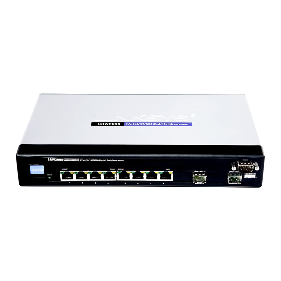
Page 8: Chapter 2: Product Overview
1000Mbps. The LEDs and ports are located on the front panel of the Switch. Use the Linksys MGBT1, MGBSX1, or MGBLH1 mini-GBIC modules with the Switch. The MGBSX1 and the MGBLH1 require fiber cabling... -
Page 9: Back Panel
Each MiniGBIC port provides a link to a high-speed network segment or individual workstation at speeds of up to 1000Mbps. Use the Linksys MGBT1, MGBSX1, or MGBLH1 mini-GBIC modules with the Switch. The MGBSX1 and the MGBLH1 require fiber cabling... -
Page 10: Chapter 3: Installation
Installation Chapter 3 Chapter 3: 1U high rack for rack-mount placement, or horizontally on the wall. Installation Desktop Placement Attach the rubber feet to the recessed areas on the Overview bottom of the Switch. This chapter will explain how to connect network devices Place the Switch on a desktop near an AC power to the Switch. -
Page 11: Rack-Mount Placement
Installation Chapter 3 Rack-Mount Placement Make sure the brackets are properly attached to the Switch. When rack-mounting the Switch, please observe the Use the appropriate screws (not included) to securely following guidelines: attach the brackets to your rack. Elevated Operating Ambient If installed in a closed •... -
Page 12: Wall-Mount Placement
Switch down until the screws fit snugly into the wall-mount slots. Proper Wall-Mount Orientation (Horizontal) NOTE: Linksys is not responsible for damages incurred by insecure wall-mounting hardware. Incorrect Wall-Mount Orientation (Vertical) Determine where you want to mount the Switch. -
Page 13: Hardware Installation
Installation Chapter 3 Hardware Installation To connect network devices to the Switch, follow these instructions: Make sure all the devices you will connect to the Switch are powered off. For 10/100Mbps devices, connect a Category 5 Ethernet network cable to one of the numbered ports on the Switch. -
Page 14: Chapter 4: Configuration Using The Console Interface
Flow control: None Start > Programs > Accessories > Communications > HyperTerminal Enter a name for this connection. In the example, the name of the connection is SRW2008. Select an icon for the application, then click OK. HyperTerminal Connection Description Screen... -
Page 15: Configuring The Switch Through The Console Interface
Configuration Using the Console Interface Chapter 4 System Configuration Menu Press the Esc button and you will return to the login screen. Use the right arrow button to navigate to Execute System Configuration Menu and press the Enter button to enter the CLI interface. System Configuration Menu options: Configuring the Switch through the System Information... - Page 16 Configuration Using the Console Interface Chapter 4 Versions Management Settings The Versions screen displays the Boot Version, Software From the Management Settings screen, you can set Serial Version, Loader Version and the Hardware Version. Port Session Configuration, Telnet Session Configuration, or Secure Telnet (SSH) Configuration.
- Page 17 Configuration Using the Console Interface Chapter 4 Telnet Configuration SSH Server Configuration SSH Configuration SSH Status On the SSH Configuration screen, you can select SSH The SSH Status screen displays whether the SSH Server is Server Configuration, SSH Server Status, SSH Crypto Key enabled, the RSA and DSA key status, and any open SSH Generation, and SSH Keys Fingerprints.
- Page 18 Configuration Using the Console Interface Chapter 4 NOTE: The Username & Password Settings screen can also be used to set passwords for other users. Security Settings The Security Settings screen enables you to configure security settings on the Switch, as well as generate and display the certificate.
- Page 19 Configuration Using the Console Interface Chapter 4 IP Address Configuration SSL Certificate Generation The IP Address Settings screen allows you to set the IP Show Certificate information for the Switch. Use the Show Certificate screen to display the internal certificate. IP Address Configuration IP Address The IP Address of the Switch is displayed.
- Page 20 Configuration Using the Console Interface Chapter 4 Ping The Ping screen displays the IP address of the location you want to contact. HTTP HTTPS Configuration Use the HTTPS Configuration screen to configure HTTPS settings. You can enable or disable the HTTPS server and Select Edit to change the IP address, and select Execute configure the port on which the session is enabled.
-
Page 21: Port Status
Configuration Using the Console Interface Chapter 4 File Management Reboot System The File Management screen allows you to upload or Select Reboot System and press the Enter key if you download files, such as the startup configuration, boot, or want to restart the Switch. You will be asked if you want to continue. - Page 22 Configuration Using the Console Interface Chapter 4 The Port Configuration screen displays the port numbers, their status, auto-negotiation status, speed and duplex mode, and status of flow control, which is the flow of packet transmissions. Select Edit and press the Enter key to make changes. When your changes are complete, press the Esc key to return to the Action menu.
-
Page 23: Chapter 5: Advanced Configuration
Advanced Configuration Chapter 5 Chapter 5: NOTE: The LEDs displayed in the web-based utility are not the same as the LEDs on the front Advanced Configuration panel of the Switch. The front panel LEDs display different status information, which is described in Chapter 2: Overview. -
Page 24: System Information
Advanced Configuration Chapter 5 Setup > Network Settings Address Mode Indicates whether the Switch is configured with a Static or Dynamic IP address (configurable from Setup - Network Settings tab). Base MAC Address This is the MAC address of the Switch. -
Page 25: Setup > Time
Advanced Configuration Chapter 5 Daylight Saving DNS Server Enter the primary DNS Server information. Click the Save Settings button to save your changes or Daylight Saving Select Daylight Saving to enable it on click Cancel Changes to discard the information. the Switch. -
Page 26: Port Configuration Detail
Advanced Configuration Chapter 5 Port Configuration Detail Speed The connection speed of the port is displayed here. The speed can be configured only when auto-negotiation is disabled on that port. Port Management > Port Configuration Port Management > Port Settings Port The number of the port. -
Page 27: Port Management > Link Aggregation
Advanced Configuration Chapter 5 Port Management > Link Aggregation Max Capability Indicates that the port speeds and • duplex mode settings can be accepted. • 10 Half Indicates that the port is advertising a 10Mbps half duplex mode setting. 10 Full Indicates that the port is advertising a 10Mbps •... -
Page 28: Port Management > Lacp
Advanced Configuration Chapter 5 Current Status Indicates if the LAG is currently operating. Reactivate Suspended LAG Reactivates a LAG if the LAG has been disabled as a result of a port lock or ACL operation. Admin Auto Negotiation Enables or disables Auto Negotiation on the LAG. -
Page 29: Vlan Management > Create Vlan
Advanced Configuration Chapter 5 VLAN Table Admin Status Indicates whether PoE is enabled or disabled on the port. The VLAN Table displays a list of all configured VLANs. The Priority Indicates the PoE priority setting of the port. The VLAN ID, VLAN Name, and status of the VLAN are displayed possible values are: Critical, High and Low. -
Page 30: Vlan Management > Ports To Vlan
Advanced Configuration Chapter 5 PVID Assigns a VLAN ID to untagged packets. The Tagged Defines the interface as a tagged member of a possible values are 2 to 4094. VLAN 4095 is defined as VLAN. All packets forwarded by the interface are tagged. per standard and industry practice as the discard VLAN. -
Page 31: Join Vlan Detail
Advanced Configuration Chapter 5 Indicates if the port is a member of a LAG. If it is a Port Indicates the port number on which GVRP is • member of a LAG, it cannot be configured to a VLAN. The enabled. -
Page 32: Statistics > Rmon History
Advanced Configuration Chapter 5 30 Sec Indicates that the RMON statistics are refreshed Refresh Now button Use this option to refresh the • every 30 seconds. statistics. • 60 Sec Indicates that the RMON statistics are refreshed Statistics > RMON History every 60 seconds. -
Page 33: Rmon History
Advanced Configuration Chapter 5 Current Number of Samples Displays the current CRC Align Errors Displays the number of CRC and Align number of samples taken. errors that have occurred on the interface since the device was last refreshed. RMON History Undersize Packets Displays the number of undersized packets (less than 64 octets) received on the interface... -
Page 34: Statistics > Rmon Events
Advanced Configuration Chapter 5 Port Displays the RMON statistics for the selected Owner Displays the device or user that defined the • port. alarm. • Displays the RMON statistics for the selected The Add to List button adds the RMON Alarms Table LAG. -
Page 35: Statistics > Port Utilization
Advanced Configuration Chapter 5 The Add to List button adds the configured RMON event 15 Sec Indicates that the statistics are refreshed every • to the Event Table at the bottom of the screen. 15 seconds. The Event Table area contains the following additional •... -
Page 36: Statistics > Gvrp Statistics
Advanced Configuration Chapter 5 Statistics > GVRP Statistics Leave All Displays the device GVRP Leave all statistics. The GVRP Error Statistics Table contains the following The GVRP Statistics screen contains device statistics for fields: GVRP. Invalid Protocol ID Displays the device GVRP Invalid Protocol ID statistics. -
Page 37: Acl > Mac Based Acl
Advanced Configuration Chapter 5 Deny Drops packets which meet the ACL criteria. Source Port Defines the TCP/UDP source port to which • the ACE is matched. This field is active only if 800/6-TCP or Shutdown Drops packet that meets the ACL •... -
Page 38: Security > Acl Binding
Advanced Configuration Chapter 5 Security > ACL Binding The MAC Based ACL screen allows a MAC based ACL to be defined. ACEs can be added only if the ACL is not bound to an interface. ACL Name Displays the user-defined MAC based ACLs. New ACL Name Specifies a new user-defined MAC based ACL name. -
Page 39: Security > Tacacs
Advanced Configuration Chapter 5 Remote Authorization Dial-In User Service (RADIUS) protocol exchanges between the device and TACACS+ servers provide additional security for networks. RADIUS server. servers provide a centralized authentication method for web access. IP Address The Authentication Server IP address. Priority The server priority. -
Page 40: Security > 802.1X Settings
Advanced Configuration Chapter 5 Security > 802.1x Settings Reauthentication Period Specifies the number of seconds in which the selected port is reauthenticated (Range: 300-4294967295). The field default is 3600 seconds. Quiet Period Specifies the number of seconds that the switch remains in the quiet state following a failed authentication exchange (Range: 0-65535). -
Page 41: Security > Multiple Hosts
Advanced Configuration Chapter 5 to that port (either it was learned on a different port, or it Trap Frequency The amount of time (in seconds) is unknown to the system), the protection mechanism is between traps. The default value is 10 seconds. invoked, and can provide various options. -
Page 42: Security > Storm Control
Advanced Configuration Chapter 5 Number of Violations Indicates the number of packets The ingress interface • that arrived on the interface in single-host mode, from Packet content • a host whose MAC address is not the supplicant MAC A combination of these attributes •... -
Page 43: Cos Default
Advanced Configuration Chapter 5 Basic Enables QoS on the interface. % of WRR Bandwidth Displays the amount of bandwidth • assigned to the queue. These values are fixed and are not Advanced Enables Advanced mode QoS on the • user defined. interface. -
Page 44: Qos > Basic Mode
Advanced Configuration Chapter 5 Modifying queue scheduling affects the queue settings The Basic Mode screen contains the following fields: globally. The Bandwidth screen is not used with the Service Trust Mode Displays the trust mode. If a packet’s CoS mode, as bandwidth settings are based on services. tag and DSCP tag are mapped to different queues, the Queue shaping can be based per queue and/or per Trust Mode determines the queue to which the packet is... -
Page 45: Out Of Profile Dscp
Advanced Configuration Chapter 5 Out of Profile DSCP New Class Map Advanced Mode > Out of Profile DSCP DSCP In Displays the DSCP In value. Advanced Mode > New Class Map DSCP Out Displays the current DSCP out value. A new Class Map Name Defines a new Class Map name value can be selected from the pull-down menu. -
Page 46: New Aggregate Policer
Advanced Configuration Chapter 5 Aggregate Policer Settings The Aggregate Policer Multiple STP Provides full connectivity for packets • button opens the New Aggregate Policer screen. allocated to any VLAN. Multiple STP is based on the RSTP. In addition, Multiple STP transmits packets New Aggregate Policer assigned to different VLANs through different MST regions. -
Page 47: Spanning Tree > Global Stp
Advanced Configuration Chapter 5 Root Forward delay (sec) Indicates the device forward Filtering Filters BPDU packets when spanning tree is • delay time. The Forward Delay Time indicates the amount disabled on an interface. This is the default value. of time in seconds a bridge remains in a listening and •... -
Page 48: Spanning Tree > Stp Port Settings
Advanced Configuration Chapter 5 Spanning Tree > STP Port Settings Forwarding Indicates that the port is in Forwarding • mode. The port can forward traffic and learn new MAC addresses. Speed Indicates the speed at which the port is operating. Path Cost Indicates the port contribution to the root path cost. -
Page 49: Spanning Tree > Mstp Properties
Advanced Configuration Chapter 5 network topologies that allow a faster STP convergence layer protocols has been configured, packets from without creating forwarding loops. each network layer protocol can be sent over the link. The link remains configured for communications until Interface Displays the port or LAG on which Rapid STP explicit LCP or NCP packets close the link, or until some... -
Page 50: Spanning Tree > Mstp Instance Settings
Advanced Configuration Chapter 5 Spanning Tree > MSTP Instance Settings Spanning Tree > MSTP Interface Settings Spanning Tree > MSTP Instance Settings Spanning Tree > MSTP Interface Settings MSTP operation maps VLANs into STP instances. Packets Network Administrators can assign MSTP Interface settings assigned to various VLANs are transmitted along different using the MSTP Interface Settings screen. -
Page 51: Multicast > Igmp Snooping
Advanced Configuration Chapter 5 Multicast > IGMP Snooping Root Provides the lowest cost path to forward packets • to root device. • Designated Indicates the port or LAG via which the designated device is attached to the LAN. Alternate Provides an alternate path to the root •... -
Page 52: Multicast > Bridge Multicast
Advanced Configuration Chapter 5 Leave Timeout Indicates the amount of time the host Dynamic Indicates port configured • waits, after requesting to leave the IGMP group and not dynamically. receiving a Join message from another station, before • Forbidden Forbidden ports are not included the timing out. -
Page 53: Snmp > Views
Advanced Configuration Chapter 5 SNMP > Views SNMP > Global Parameters Local Engine ID Indicates the local device engine ID. The SNMP > Views field value is a hexadecimal string. Each byte in hexadecimal character strings consists of two hexadecimal digits. Each SNMP Views provide access or block access to device byte can be separated by a period or a colon. -
Page 54: Snmp > Group Profile
Advanced Configuration Chapter 5 SNMP > Group Profile Notify Sends traps for the assigned SNMP view. • SNMP > Group Membership SNMP > Group Profile The Group Profile screen provides information for creating SNMP > Group Membership SNMP groups and assigning SNMP access control privileges The Group Membership screen provides information to SNMP groups. -
Page 55: Snmp > Communities
Advanced Configuration Chapter 5 performed via HMAC-SHA-96 authentication. Basic Enables SNMP Basic mode for a selected community and contains the following fields: Password Define the local user password. Local user passwords can contain up to 159 characters. Access Mode Defines the access rights of the community. The possible field values are: Authentication Key Defines the HMAC-MD5-96 or... -
Page 56: Advanced Table
Advanced Configuration Chapter 5 Advanced Table The Add to List button adds the Notification Filter configuration to the Notification Filter Table at the bottom Management Station Displays the management station of the screen. IP address for which the basic SNMP community is SNMP >... -
Page 57: Admin > User Authentication
Advanced Configuration Chapter 5 UDP Port Displays the UDP port used to send notifications. Password Specifies the new password. The password The default is 162. is not displayed. As it entered an “*” corresponding to each character is displayed in the field. (Range: 1-159 Filter Name Indicates if the SNMP filter for which the characters) -
Page 58: Query
Advanced Configuration Chapter 5 Delete on Reset The MAC address is deleted when address is erased, and includes parameters for querying • the device is reset. and viewing the Dynamic MAC Address table. The Dynamic MAC Address table contains address parameters by which •... -
Page 59: Admin > Port Mirroring
Advanced Configuration Chapter 5 all error reporting. For example, Syslog and local device Source Port Defines the port to which traffic is mirrored. reporting messages are assigned a severity code, and Type Indicates the port mode configuration for port include a message mnemonic, which identifies the source mirroring. -
Page 60: Admin > Save Configuration
Advanced Configuration Chapter 5 Via HTTP Cable Length This is the approximate length of the cable. The Cable Length test can be performed only when the This HTTP Firmware Upgrade screen is used for saving port is up and operating at 1Gbps. configuration information using your web browser. -
Page 61: Admin > Reboot
Advanced Configuration Chapter 5 NOTE: When downloading a configuration file, NOTE: Restoring the factory defaults will make sure that it is a valid configuration file. If erase all configuration settings that you have you have edited the file, ensure that only valid made. -
Page 62: Admin > Memory Logs
Advanced Configuration Chapter 5 Admin > Memory Logs Log Index Displays the log number. Log Time Displays the time at which the log was The Memory Log screen contains all system logs in a generated. chronological order that are saved in RAM (Cache). Severity Displays the log severity. -
Page 63: Appendix A: About Gigabit Ethernet And Fiber Optic Cabling
In Europe, the round ST connector is more prevalent. For Gigabit Ethernet, you must use the Linksys MGBT1, MGBSX1, or MGBLH1 miniGBIC modules with the Linksys Gigabit Switches. The MGBSX1 and the MGBLH1 require fiber cabling with LC connectors, and the MGBT1 requires a Category 5e Ethernet cable with an RJ-45 connector. -
Page 64: Appendix B: Introduction
Filename: field, enter the file path for the file to be downloaded or click Browse to locate the file. Only valid files, with a *.ros or *.rfb suffix, that have been provided by Linksys, can be downloaded. Auto-Boot Messages When the auto-boot message appears, press the... - Page 65 Downloading Using Xmodem Appendix B Press Send and the software is downloaded. Download After the software has been downloaded, the device will reboot automatically. 8-Port 10/100/1000 Gigabit Switch with Webview...
-
Page 66: Appendix C: Glossary
WEB: For additional terms, please visit the Browser An application program that provides a way to glossary at www.linksys.com/glossary look at and interact with all the information on the World Wide Web. Access Mode Specifies the method by which user access Bridge A device that connect two networks. - Page 67 Glossary Appendix C CoS (Class of Service) The 802.1p priority scheme. CoS Full Duplex The ability of a networking device to receive provides a method for tagging packets with priority and transmit data simultaneously. information. A CoS value between 0-7 is added to the GARP (General Attributes...
- Page 68 Glossary Appendix C MAC (Media Access Control) Address The unique RADIUS (Remote Authentication Dial-In User address that a manufacturer assigns to each networking Service) A protocol that uses an authentication server to device. control network access. Mask A filter that includes or excludes certain values, for RJ-45 (Registered Jack-45) An Ethernet connector that example parts of an IP address.
- Page 69 Glossary Appendix C TCP (Transmission Control Protocol) A network protocol for transmitting data that requires acknowledgement from the recipient of data sent. TCP/IP (Transmission Control Protocol/Internet Protocol) A set of instructions PCs use to communicate over a network. Telnet A user command and TCP/IP protocol used for accessing remote PCs.
-
Page 70: Appendix D: Specifications
Appendix D Appendix D: Specifications Specifications RMON Embedded Remote Monitoring (RMON) Software Agent Model SRW2008 Supports four RMON Groups Ports 8 RJ-45 Connectors for (History, Statistics, Alarms, and 10BASE-T/100BASE-TX/ Events) for Enhanced Traffic 1000Base-T with 2 shared SFP Management, Monitoring, and ports on port 7 and 8 (combo Analysis. - Page 71 Specifications Appendix D Storm Control Broadcast, Multicast and Operating Humidity 10 to 90% Noncondensing Unknown Unicast Storage Humidity 10 to 95% Noncondensing Spanning Tree IEEE 802.1d Spanning Tree, IEEE 802.1w Rapid Spanning Specifications are subject to change without notice. Tree, IEEE 802.1s Multiple Spanning Tree IGMP Snooping IGMP (v1/v2) Snooping...
- Page 72 Specifications Appendix D Model SRW2008MP (History, Statistics, Alarms, and Events) for Enhanced Traffic Ports 8 RJ-45 Connectors for Management, Monitoring, and 10BASE-T/100BASE-TX/ Analysis. 1000Base-T with 2 shared SFP ports on port 7 and 8 (combo Firmware Upgrade Web Browser Upgrade (HTTP) port) TFTP Upgrade Console Port...
- Page 73 Specifications Appendix D traffic to only the requestors. Model SRW2008P Support 256 multicast groups.. Ports 8 RJ-45 Connectors for 10BASE-T/100BASE-TX/ 1000Base-T with 2 shared SFP Priority levels 4 Hardware Queues ports on port 7 and 8 (combo Scheduling Priority Queueing and port) Weighted Round Robin (WRR) Console Port...
- Page 74 Specifications Appendix D Supports four RMON Groups bandwidth-intensive video (History, Statistics, Alarms, and traffic to only the requestors. Events) for Enhanced Traffic Support 256 multicast groups.. Management, Monitoring, and Analysis. Priority levels 4 Hardware Queues Firmware Upgrade Web Browser Upgrade (HTTP) Scheduling Priority Queueing and TFTP Upgrade...
-
Page 75: Appendix E: Warranty Information
CONDITIONS, REPRESENTATIONS AND WARRANTIES, and the web pages referred to herein may be updated by INCLUDING, BUT NOT LIMITED TO, ANY IMPLIED Linksys from time to time; the version in effect at the date WARRANTY OF NON-INFRINGEMENT, ARE DISCLAIMED. of purchase shall apply. -
Page 76: Technical Support
RMA number and dated proof of original purchase will be rejected. Do not include any other items with the product you are returning to Linksys. Defective product covered by this limited warranty will be repaired or replaced and returned to you without charge. -
Page 77: Appendix E: Regulatory Information
Regulatory Information Appendix E Industry Canada Statement Appendix E: Regulatory Information This Class A digital apparatus complies with Canadian ICES-003. Operation is subject to the following two conditions: FCC Statement This device may not cause interference and This equipment has been tested and complies with This device must accept any interference, including the specifications for a Class A digital device, pursuant interference that may cause undesired operation of... -
Page 78: User Information For Consumer Products Covered By Eu Directive 2002/96/Ec On Waste Electric And Electronic Equipment (Weee)
úřady. Správná likvidace a recyklace pomáhá předcházet Linksys products. Consumers are required to comply with potenciálním negativním dopadům na životní prostředí a lidské this notice for all electronic products bearing the following zdraví. - Page 79 Regulatory Information Appendix E Eesti (Estonian) - Keskkonnaalane informatsioon Français (French) - Informations environnementales Euroopa Liidus asuvatele klientidele pour les clients de l’Union européenne Euroopa Liidu direktiivi 2002/96/EÜ nõuete kohaselt on La directive européenne 2002/96/CE exige que l’équipement seadmeid, millel on tootel või pakendil käesolev sümbol sur lequel est apposé...
- Page 80 Regulatory Information Appendix E Lietuvškai (Lithuanian) - Aplinkosaugos informacija, Nederlands (Dutch) - Milieu-informatie voor klanten skirta Europos Sąjungos vartotojams in de Europese Unie Europos direktyva 2002/96/EC numato, kad įrangos, kuri ir De Europese Richtlijn 2002/96/EC schrijft voor dat apparatuur die kurios pakuotė...
- Page 81 ľudí. Ak máte záujem o podrobnejšie WEB: For additional information, please visit informácie o likvidácii starého zariadenia, obráťte sa, prosím, na www.linksys.com/international miestne orgány, organizácie zaoberajúce sa likvidáciou odpadov alebo obchod, v ktorom ste si produkt zakúpili. 8-Port 10/100 Ethernet Switch with Webview...
-
Page 82: Appendix I: Contact Information
Appendix I Appendix I: Region Web Address Contact Information www.linksys.com/EGen/support Egypt (English) www.linksys.com/EE/support Estonia If you experience problems with any Linksys product, you can contact support by visiting the appropriate website: Ethiopia www.linksys.com/ET/support Region Web Address Finland www.linksys.com/FI/support Algeria (Arabic) www.linksys.com/DZar/support... - Page 83 Malaysia www.linksys.com/MY/support www.linksys.com/SAen/support (English) Mauritius www.linksys.com/MU/support Serbia & www.linksys.com/CS/support Montenegro Mexico www.linksys.com/MX/support www.linksys.com/SC/support Seychelles Morocco (Arabic) www.linksys.com/MAar/support www.linksys.com/SG/support Singapore Morocco (English) www.linksys.com/MAen/support Slovakia www.linksys.com/SK/support Namibia www.linksys.com/NA/support Slovenia www.linksys.com/SI/support www.linksys.com/NL/support Netherlands South Africa www.linksys.com/ZA/support www.linksys.com/NZ/support New Zealand Spain www.linksys.com/ES/support www.linksys.com/NG/support Nigeria Sweden www.linksys.com/SE/support...
Need help?
Do you have a question about the SRW2008 and is the answer not in the manual?
Questions and answers