
Related Manuals for MDS MDS Orbit MCR-4G

Summary of Contents for MDS MDS Orbit MCR-4G
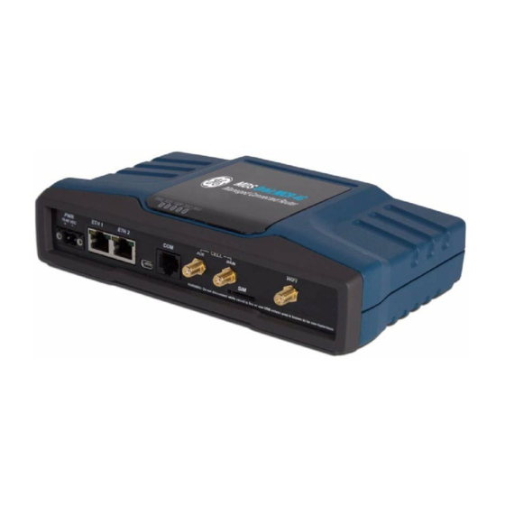
- Page 1 Orbit MCR-4G Managed Connected Router 4G and WiFi MDS 05-6628A01, Rev. C NOVEMBER 2013...
- Page 2 Quick-Start instructions for this product are contained in publication 05-6702A01. Visit our website for downloadable copies of all documentation at www.gemds.com.
-
Page 3: Table Of Contents
TABLE OF CONTENTS 1.0 INTRODUCTION ........................1 1.1 About This Manual ........................1 Software Command Notations ......................1 2.0 PRODUCT DESCRIPTION....................3 2.1 Key Features ..........................3 2.2 Interface Types ..........................3 2.3 Typical Application ......................... 3 2.4 Connectors and Indicators ......................4 Grounding Considerations ....................... - Page 4 Copyright and Trademark This manual and all software described herein is protected by Copyright: 2013 GE MDS, LLC. All rights reserved. GE MDS, LLC reserves its right to correct any errors and omissions in this publi- cation. MDS Orbit MCR Technical Manual...
-
Page 5: Fcc Part 15 Notice
Cet appareil numérique de la classe A est conforme à la norme NMB-003 du Canada. Operational Safety Notices The MDS Orbit MCR-4G may not be used in an environment where radio frequency equipment is prohibited or restricted in its use. This typically includes aircrafts, airports, hospitals, and other sen- sitive electronic areas. - Page 6 Do not operate RF devices in an environment that may be susceptible to radio interference resulting in danger, specifically: • Areas where prohibited by law Follow any special rules and regulations and obey all signs and notices. Do not use the MCR-4G when you suspect that it may cause interference or danger.
-
Page 7: Environmental Information
These systems will reuse or recycle most of the materials found in this equipment in a sound way. Please contact GE MDS or your supplier for more information on the proper dis- posal of this equipment. - Page 8 A power connector with screw-type retaining screws as supplied by GE MDS must be used. Do not disconnect equipment unless power has been switched off or the area is known to be non-hazardous.
-
Page 9: Introduction
It serves the need for localized WiFi communications with a cellular back-up or backhaul option, while providing the extended temperature range and industrial-grade packaging inherent to GE MDS products. These features allow the best use of communication options at each installation site. - Page 10 In the Device Management section of this manual (Section 3.0), there are a number of command strings where information is presented by the unit, and a reply is required from the user. In such cases, information from the unit is shown in a non-bolded font, and the user response is shown in bold. For example: (none) login: admin Further, in some cases, command lines will be shown with non-bolded, italicized text contained within the string.
-
Page 11: Product Description
2.0 PRODUCT DESCRIPTION The MCR-4G is a rugged networking router providing comprehensive solutions for IP/Ethernet, serial, and machine-to-machine wireless communication. This industrial package provides integrated 4G LTE wireless technology and connectivity for Ethernet and serial devices requiring secure operation. 2.1 Key Features MCR units include the following key features: •... -
Page 12: Connectors And Indicators
Invisible place holder Figure 2. Typical MCR Application 2.4 Connectors and Indicators shows the unit’s front panel connectors and indicators. These items are referenced in the Figure 3 text that follows. The unit’s LED Indicator Panel is described in Table 4 on Page LED Indicator Panel Mini USB... - Page 13 PWR—Two-conductor DC input connection. The unit includes a 6-foot (1.83 meter) power cable suitable for indoor or outdoor use when properly connected. The DC power connector (Figure 4) is keyed, and can only be inserted one way. Invisible place holder Lead Binding Screws (2)
- Page 14 By default, the port is enabled for local console control. The COM port serves as the primary interface for connecting the unit to an external DTE serial device supporting RS-232 or RS-485. If necessary, an adapter may be used to convert the unit’s RJ-45 serial jack to a DB-9F type (GE MDS 73-2434A12). NOTE: Not all PCs include a serial port.
- Page 15 Table 2. COM1/2 Port Pin Details (RS-232) (Continued) Input/Output Pin Description Number RXD (Received Data)—Supplies received data to the connected device TXD (Transmitted Data)—Accepts TX data from the connected device CTS (Clear to Send) RTS (Ready to Send) Table 3. COM1 Port Pin Details (RS-485) Input/Output Pin Description Number...
- Page 16 MIMO receive operation (diversity) with standard 4G modules, improving signal quality in many installations. In general, both antennas should always be used for cellular operation. The GE MDS part number for this antenna type is 97-2485A04. Figure 5. Directly-Connected Cellular Antenna (Typical Style) (GE MDS Part No.
-
Page 17: Grounding Considerations
LED Status Indicators—The LEDs on the unit provide visual indications of the status of the device as shown in Figure 7 and explained in Table 4 which follows. Figure 7. LED Status Indicators Table 4. Description of LED Status Indicators LED Name LED State Description... -
Page 18: Mounting Options
2.4.2 Mounting Options The unit may be mounted with flat mounting brackets or an optional 35 mm DIN rail attachment. Figure 8 shows the mounting dimensions for a unit equipped with flat mounting brackets. Invisible place holder 8.5” (21.59 cm) 9.25”... -
Page 19: Antenna Planning & Installation
Indoor use case: 1. This scenario employs direct mounting of an LTE paddle antenna (GE MDS PN: 97-2485A04) on the Main and Aux Cell channels, and cabled mounting of the Wi-Fi antenna (GE MDS PN: 97-4278A34) using a magnetic mount (GE MDS PN: 97-4278A78). - Page 20 External enclosures—If the system is going to be installed in a weathertight enclosure and mounted outside in the elements, cabled use of external LTE antennas (GE MDS PN: 97-2485A05) on the Main and AUX Cell ports, with cabled use of the External Wi-Fi antenna (GE MDS PN: 97-4278A48) is a good solution.
-
Page 21: Accessories And Spares
2.4.5 Accessories and Spares Table 6 lists common accessories and spare items for use with the MCR-4G. GE MDS also offers an Acces- sories Selection Guide listing an array of additional items that may be used with the product. Contact your factory representative or visit to obtain a copy of the guide. -
Page 22: Device Management
Not all PCs include a serial port. If one is not available, a USB port may be used, along with a USB-to-Serial adapter (with appropriate driver software). Adapters are available from many manufacturers, including GE MDS. The MCR Orbit’s USB port can be used to access the device management console by using a Mini-USB cable between the device and a PC. -
Page 23: Setting Basic Parameters-First Steps
Double check to be sure they are correct. If necessary, an adapter may be used to convert the unit’s RJ-45 serial jack to a DB-9F type (GE MDS part no. 73-2434A12). If no serial port exist on the PC, a USB-to-serial adapter cable may be used to connect to the MCR unit, or a Mini-USB cable may be connected between the MCR’s USB... -
Page 24: One-Time "Recovery" Passwords
3.1.4 One-Time “Recovery” Passwords The MDS Orbit platform employs extensive security measures to prevent unauthorized access. As such, there are no hidden manufacturer passwords or other “backdoors” found in less secure products. If a pass- word is lost, there is no way to access the unit, except by using a one-time password (OTP) for recovery. This must be established by the user beforehand. -
Page 25: Pre-Configured Settings
Enter the command where X is a number request system recovery one-time-passwords delete identifier X from the currently available one-time passwords. This identifier is not reused. If all five passwords have been created, then ID 1 can be deleted, and the next created password will be at ID 6. The current list of passwords may be viewed by issuing the command show system recovery one-time-pass- . -
Page 26: Yang Interface
4. set interfaces interface Cell ipv4 dhcp 5. set interfaces interface Cell filter input IN_UNTRUSTED 6. set interfaces interface Cell filter output OUT_UNTRUSTED 7. set interfaces interface Cell nat source MASQ 8. set services serial console serial-ports [ COM1 USB1 ] 9. -
Page 27: Cli Login Prompt
When viewing the configuration, the nodes that have default values and have not been explicitly set by the user are not displayed. Users can selectively view these defaulted values by using option on the CLI. details command can be used to view configuration data. Notice that the information displayed is dif- show ferent, depending on which mode the CLI is in;... - Page 28 Step 3: Change the device name by typing in the following, followed by enter: set system name Device539 admin@(none) 05:31:14% set system name Device539 [ok][2012-06-20 05:32:45] [edit] admin@(none) 05:32:45% Step 4: Verify the change looks correct by reading the data back using the following, followed by the enter key: show system name admin@(none) 05:32:53% show system name...
- Page 29 CLI Quick Reference Table Table 7 provides a summary listing of commonly-needed tasks and the appropriate commands to enter. The table can be used as a quick reference before consulting the more detailed information which follows in this section. Each CLI command is proceeded by the symbol for operational command, or for a configura- >...
- Page 30 Specific Examples Example #1 Figure 12, the MCR-4G is functioning as a WiFi Access Point to provide connectivity between a set of laptops and a handheld device. The MCR-4G is also acting as a DHCP server for the laptops and handheld device.
- Page 31 Example #2 Figure 13, there are two MCR-4G devices, one acting as a WiFi Access Point, the other as a WiFi Station. Together, the MCR-4G devices are providing a wireless bridge between the laptop and the SCADA device. Invisible place holder Figure 13.
- Page 32 Example #3 Figure 14 shows the MCR-4G #2 device acting as a terminal server to provide connectivity to the serial-based SCADA device via UDP. Figure 14 NOTE: The configuration for MCR-4G #1 in is identical to the configuration shown in the previous example (Example #2).
-
Page 33: Operational Topic Areas
Example #4 Figure 15, the MCR-4G provides internet access for a laptop that is accessing a public web page. Invisible place holder Figure 15. Example 4: Unit Providing Internet Access for Laptop SIM Type: In this scenario, the MCR-4G has a SIM card installed that simply provides Internet access. The following commands will configure the MCR-4G for this scenario. -
Page 34: Serial Console
115200 bps with 8N1 format. A mini-USB-to-USB cable may also be used to connect to a Com- puter in case no serial port exists. If a mini-USB connection is used, the computer must contain the appro- priate device driver. A driver for serial operation can be found on GE MDS website. Configuring... -
Page 35: Network
Network Understanding The unit has multiple network interfaces including LAN, Cellular, and WiFi. Each of these has numerous networking features and each feature is described in a separate section on the following pages: • Static or dynamic IP addressing (DHCP) for each interface •... - Page 36 bridgeStatus stp port ETH1 number priority state forwarding path-cost designated-root 7035.04fe7fe36980 designated-cost designated-bridge 8000.0002fd5dd280 designated-port 32788 bridgeStatus stp port ETH2 number priority state disabled path-cost designated-root 8000.00063d06ea99 designated-cost designated-bridge 8000.00063d06ea99 designated-port 32770 bridgeStatus stp port GEMDS_ORBIT interfaces interface Cell oper-status not-present if-index lower-layer-if [...
- Page 37 statistics out-discards 0 statistics out-errors 0 eth-phy-status "10 Mb, Half Duplex" system-device eth0 interfaces interface ETH2 oper-status lower-layer-down if-index phys-address 00:06:3d:06:ea:99 lower-layer-if [ speed 10000000 statistics discontinuity-time 2013-09-09T16:16:13-04:00 statistics in-octets 0 statistics in-unicast-pkts 0 statistics in-multicast-pkts 0 statistics in-discards 0 statistics in-errors 0 statistics out-octets 0 statistics out-unicast-pkts 0...
-
Page 38: Lan
Understanding The unit has external Local Area Network (LAN) ports that can be used to connect to a local LAN. It sup- ports both IPv4 and IPv6 addresses and may be assigned multiple IP addresses. The LAN port can be assigned static IP addresses or a dynamically allocated address can be assigned using DHCP. - Page 39 Monitoring Ensure the CLI is in Operational mode. Follow the example below to view the state and statistics of the ETH1 port: admin@(none) 11:41:58> show interfaces interface ETH1 interfaces interface ETH1 oper-status if-index phys-address 00:06:3d:06:ea:99 lower-layer-if [ speed 10000000 statistics discontinuity-time 2013-09-09T16:16:13-04:00 statistics in-octets 3435997213 statistics in-unicast-pkts 37738358 statistics in-multicast-pkts 0...
-
Page 40: Vlan Operation
VLAN Operation Understanding Virtual Local Area Networks (VLANs) are generic interface types in the MCR-4G, and can be assigned unique IP addresses. They are treated the same as any other interface type, but they offer a way to link traffic between interface ports. -
Page 41: Cell
Cell Understanding The unit incorporates a 4G LTE module capable of operation on Verizon Wireless LTE/CDMA network (LTE 700 Mhz Band 13) in the United States. The unit supports routing of TCP/UDP/IP data from the Cel- lular WAN network interface to any of the other network interfaces (including WiFi or LAN) using the IPsec VPN or network address and port translation (NAPT) feature and to the COM1 (or COM2) serial port using the terminal server service. - Page 42 LTE Recovery The cellular modem used inside the unit may occasionally remain in a 3G (EVDO-REV A) service state and not transition to 4G LTE. The firmware incorporates a recovery mechanism to recover from this condition. If the cellular modem has been in 3G coverage for more than 15 minutes, the firmware resets the modem to bring it back into LTE service state.
- Page 43 Monitoring Ensure the CLI is in Operational mode. Follow the example below to view the cellular interface state and statistics: admin@(none) 08:33:32> show interfacesshow interfaces interface Cell interfaces interface Cell oper-status if-index phys-address 00:15:ff:75:93:50 lower-layer-if [ ] statistics discontinuity-time 2013-03-18T09:07:53+00:00 statistics in-octets 3847 statistics in-unicast-pkts 26 statistics in-multicast-pkts 0...
-
Page 44: Wifi
WiFi Understanding The internal WiFi module has FCC modular approval and may only be used with one of the GE MDS approved antennas (see 802.11 WiFi Module Specifications below). The WiFi antenna is connected to the reverse-SMA connector on the unit’s front panel. Only these antennas may be used. The WiFi module can be configured to operate as an 802.11b/g/n Access Point or Station. - Page 45 Privacy Mode Configuration The default privacy mode is wpa2-personal . (The privacy mode in the previous example was set to none The following configures the unit to use WPA2-Personal security with the default of CCMP/AES encryp- tion and disables the broadcasting of the SSID. admin@(none) 17:08:10% set interfaces interface Wi-Fi wifi-config ap-config ap...
-
Page 46: Other Configuration
channel operation-mode 80211g; dtim-period rts-threshold 2347; fragm-threshold 2346; [ok][2013-09-24 17:09:16] admin@(none) 17:09:30% commit Commit complete. [ok][2013-09-24 17:09:31] Other configuration The following configures the device to broadcast its SSID, support 802.11b/g/n modes, and operate on channel 3. admin@(none) 17:09:14% set interfaces interface Wi-Fi wifi-config ap-config operation-mode 80211n channel 3 ap... -
Page 47: Station Mode
Station Mode This sets the unit to act as a WiFi station to connect to an AP with and WPA2 Personal security. somessid Wi-Fi admin@(none) 17:28:10% set interfaces interface wifi-config mode station station-config ap somessid somepassphrase enabled true privacy-mode wpa2-personal psk-config psk encryption ccmp Wi-Fi admin@(none) 17:28:23% show interfaces interface... - Page 48 Station Mode The following shows status when connected to a configured AP. admin@(admin) 10:04:42> show interfaces interface Wi-Fi wifi-status wifi-status serial-number N722M33NU000628 wifi-status mode Station wifi-status tx-power 15 wifi-status channel 4 wifi-status station-status ssid somessid wifi-status station-status bssid 00:19:70:2c:40:3f wifi-status station-status rssi -58 wifi-status station-status authenticated true wifi-status station-status authorized true wifi-status station-status inactive 29270...
-
Page 49: Bridging
Bridging Understanding The unit supports transparent bridging of LAN and WiFi networks. The bridge forwards traffic between LAN and WiFi networks at the layer-2 of OSI model. This allows LAN and WiFi clients to be in the same IP sub-network. The bridge learns the clients’... - Page 50 Invisible place holder Figure 16. Bridging Functions Diagram Configuring Creating a bridge interface and assigning it an IP address: admin@(none) 00:02:09% set interfaces interface myBridge virtual-type bridge admin@(none) 00:02:20% set interfaces interface myBridge bridge-settings ageing-time 500 admin@(none) 00:22:26% set interfaces interface myBridge ipv4 address 192.168.1.10 prefix-length 24 Adding LAN (ETH1) interface to the bridge: admin@(none) 00:06:20% set interfaces interface myBridge bridge-settings members port ETH1 Adding WiFi interface to the bridge (Access Point):...
- Page 51 Monitoring Ensure the CLI is in operational mode. Follow the example below to view the state and statistics of a bridge. In this example, bridge (Bridge) is bridging the LAN (ETH1). admin@(none) 10:14:19> show interfaces interface Bridge interfaces interface Bridge oper-status if-index phys-address 00:06:3d:06:ea:99...
-
Page 52: Routing
Routing Understanding The unit can be configured to route IP packets between routed interfaces. Configuring a default static route: admin@(none) 00:50:52% set routing static-routes ipv4 route 1 dest-prefix 0.0.0.0/0 next-hop 192.168.1.10 Configuring a static host route: % set routing static-routes ipv4 route 2 dest-prefix 10.2.3.1/32 next-hop 192.168.1.9 admin@(none) 00:04:57% show routing static-routes ipv4 { route 1 {... -
Page 53: Firewall And Nat
Firewall and NAT Understanding The MCR incorporates a firewall service that provides the following functionality: 1. Packet filtering to permit or deny incoming or outgoing traffic on an interface. 2. Network Address Translation (NAT) • Source NAT - Masquerading • Destination NAT – Port Forwarding Packet Flow This section provides a simplified view of packet flow for various categories of traffic flows going in and out of the MCR unit. - Page 54 Figure 20 shows the flow of packets being port-forwarded (DNAT’ed) through the MCR unit. For example, TCP traffic arriving at the cellular interface and getting port forwarded to a private host connected to the local Ethernet interface. Invisible place holder Figure 20.
-
Page 55: Packet Filtering
Packet Filtering Understanding Packet filtering allows configuring and applying a packet filter (also called Access Control List, or ACL) to incoming or outgoing traffic on an interface. A filter is a set of one or more rules. Each rule consists of two parts: •... - Page 56 Packet filter configuration on MCR involves following these high level steps: 1. Create a filter, decide on default policy of the filter. For example, there are usually two ways to organize a filter: a. Create a “restrictive” filter i.e. the last rule in the filter (also called “default policy” of filter) is to deny traffic and rules are added to specifically permit the traffic.
- Page 57 NOTE: The rule stated in step 5 permits SSH or NETCONF connection addressed to the cellular inter- face’s IP address. If it is desired that SSH or NETCONF connection only be allowed via the VPN tunnel, then ipsec match criteria described below should be used instead of the rule stated in step admin@(none) 19:33:20% set services firewall filter IN_UNTRUSTED rule 3 match ipsec direction in tunnel-src-address 10.150.1.1/32 tunnel-dst-address 10.150.1.10/32 admin@(none) 19:33:20% set services firewall filter IN_UNTRUSTED rule 3 actions action accept...
-
Page 58: Network Address Translation (Nat)
Network Address Translation (NAT) Understanding Network address translation allows one to map private IP addresses to public IP addresses and vice versa. There are two basic kinds of network address translation: • Source NAT • Destination NAT Source NAT Source NAT performs translation of source IP address of the traffic egressing an interface. This is typically used to provide many-to-one translation (also called masquerading) of a private network behind MCR to allow hosts on that private network to access a host (say HOST-B) on the public network. -
Page 59: Configuration Hierarchy
Configuring Configuration Hierarchy services { firewall nat { source { rule-set <name> { rule <id> { match { src-address { not <boolean>; add-interface-address <true|false>; address <network/prefix>; address-range <to/from>; address-set <name> { add-interface-address <true|false> not <boolean> dst-address { not <boolean>; add-interface-address <true|false>; address <network/prefix>;... - Page 60 3. Create rule for masquerading admin@(none) 19:33:20% set services firewall nat source rule-set MASQ rule 1 source-nat interface 4. Apply this source NAT rule-set to the cellular interface. admin@(none) 19:33:20% set interfaces Cell nat source MASQ 5. Commit configuration and exit configuration mode. admin@(none) 19:33:20% commit Commit complete.
- Page 61 Configuring Configuration Hierarchy services { firewall nat { destination { rule-set <name> { rule <id> { match { src-address { not <boolean>; add-interface-address <true|false>; address <network/prefix>; address-range <to/from>; address-set <name> { add-interface-address <true|false> not <boolean> dst-address { not <boolean>; add-interface-address <true|false>; address <network/prefix>;...
- Page 62 3. Create rule for port forwarding Modbus TCP traffic coming into cellular interface on port 512 to port 5512 on private HOST-1. admin@(none) 19:33:20% set services firewall nat destination rule-set IO_SERVICES rule 1 match pro- tocol tcp dst-address address 10.150.1.1/32 Value for ‘services firewall nat destination rule-set IO_SERVICES rule 1 destination-nat-address’(<IP address>): 192.168.1.1 admin@(none) 19:33:20% set services firewall nat destination rule-set IO_SERVICES rule 1 match...
-
Page 63: Vpn
Understanding The MCR supports standards-based IPsec Virtual Private Network (VPN) technology to securely connect remote private network (LAN or WiFi) with the customer’s backoffice/data center private network see Figure 24). This allows IP traffic from/to devices connected to either LAN, WiFi or Serial port of the MCR to securely flow to/from back-office applications via a secure tunnel through a public cellular network. - Page 64 The process of IPsec VPN connection establishment consists of following phases: • IKE Phase-1 (IKE security negotiation) - Negotiate how IKE should be protected • IKE Phase-2 (IPsec Security Association) - Negotiate how IPsec should be protected - Derive fresh keying material from the key exchange in phase-1, to provide session keys to be used in the encryption - and authentication of the VPN data flow •...
- Page 65 connection <name> { ike-peer <reference-to-ike-peer>; ipsec-policy <reference-to-ipsec-policy>; local-ip-subnet <ip address/len>; remote-ip-subnet <ip address/len>; failure-retry-interval is-out-of-band-ima <true|false> local-source-ip-address <ip address>; periodic-retry-interval <mins>; Firewall Filters for the Cellular Interface When setting up IPsec VPN over a Cellular interface, the following firewall filters are recommended to be configured and applied to the cellular interface.
- Page 66 rule 2 { match { ipsec { direction out; tunnel-src-address <CELL INTERFACE IP ADDRESS>/32; tunnel-dst-address <VPN SERVER IP ADDRESS>/32; actions { action accept; rule 10 { match { protocol all; actions { action drop; VPN configuration involves the following high level steps: 1.
- Page 67 4. Enable VPN service admin@(none) 20:38:44% set services vpn enabled true 5. Create IKE policy with auth-method “public-key encryption”. admin@(none) 19:33:29% set services vpn ike policy IKE-POLICY-1 auth-method pub-key 6. Configure Public Key Infrastructure (PKI) security credentials a. Certificate type as “rsa” if RSA public key encryption based certificates are being used. b.
- Page 68 2. Create an IPsec policy and configure the following ciphersuite to be included as proposal for IKE phase-2 negotiation: • Encryption Algorithm = AES 256 Bit in CBC mode • Message Authentication Algorithm = HMAC using SHA256 digest • Diffie-Hellman Group = DH-14 (group 14 modp2048) admin@(none) 19:33:29% set services vpn ipsec policy IPSEC-POLICY-1 ciphersuite AES256_CBC-SHA256-DH14 encryption-algo aes-256-cbc admin@(none) 19:33:29% set services vpn ipsec policy IPSEC-POLICY-1 ciphersuite...
- Page 69 Monitoring Ensure the CLI is in operational mode. Follow the example below to view the VPN connection state (con- necting, connected or disconnected). The failure-reason displays the reason for last connection failure. admin@(none) 20:40:45> show services vpn VPN-GWY-CONN-1 services vpn ipsec ipsec-status connection state connecting failure-reason...
-
Page 70: Dns
Understanding Domain Name System (DNS) servers can be configured on the unit to facilitate the resolution of domain names to IP addresses. NOTE: Manual configuration of DNS overrides any DNS settings obtained via DHCP. Configuring The following example shows how to configure a DNS server with IP address 192.168.1.2 on the MCR. Note that the “search”... -
Page 71: Dhcp Service
DHCP Service Understanding The unit can be configured to act as a DHCP server. When enabled, this service will respond to DHCP requests from any interface. Configuring The following shows an example of configuring DHCP service on the unit. The unit will administer IPv4 addresses from the 192.168.x.x network when requests are received from DHCP clients. - Page 72 Terminal Service Understanding The unit allows the setup of the COM ports as a terminal server that passes data to/from the serial port to network interfaces. The serial port must be configured to do this, in addition to the baud rate and data format. The data from the serial port is treated as a seamless stream;...
-
Page 73: Iperf Service
Iperf Service Understanding Iperf service allows one to receive TCP traffic from remote host running iperf. Currently, iperf service is hardcoded to act only as a TCP server listening on port 5001. Configuring The following shows how to enable iperf service: admin@(none) 22:04:32% set services iperf enabled true admin@(none) 22:04:32% commit Commit complete. -
Page 74: Date, Time And Ntp
Date, Time and NTP Understanding The date and time can be set on the MCR using a manually configured value or automatically via Network Time Protocol (NTP). The NTP settings take precedence over the manual settings. If NTP is enabled, then the user will not be able to set the date and time manually. -
Page 75: Geographical-Location
Geographical-location The geographical-location of the unit can be configured as shown below: admin@(none) 00:50:46% set system geographical-location altitude 1.0 latitude 43.117807 longitude -77.611896 [ok][2012-06-19 00:56:00] [edit] admin@(none) 00:56:00% commit Commit complete. [ok][2012-06-19 00:56:05] [edit] admin@(none) MDS 05-6628A01, Rev. C MDS Orbit MCR Technical Manual... -
Page 76: User Management And Access Controls
User Management and Access Controls Understanding There are three user accounts/roles (administrator, technician, and operator) for management access. Users in the admin group have the highest privilege and can read everything in the tree that is readable, write everything that is writable, and can execute any of the requests. Users in the tech group have less access than admin. - Page 77 Monitoring Ensure the CLI is in operational mode. Follow the example below to see the history of login attempts by reviewing the event log: admin@(none) 01:21:48> show logging event-log event-type console_login logging event-log 62625 time-stamp 2011-12-21T01:18:08.985996+00:00 priority notice event-type console_login status success message...
-
Page 78: Login-Lockout
Login-Lockout Understanding The unit has protections against repeated login attempts. The max-login-attempts configuration determines the number of failed logins that can occur in succession before the unit disables the ability to login for a specified amount of time. The amount of time is determined by failed-login-lockout-time, which represents the time in seconds. -
Page 79: Radius
A RADIUS server must be con- figured to provide the user’s authentication group in its authentication reply via a GE MDS vendor attribute. This can be configured in freeradius (an open source RADIUS server) by using the following dictionary file:... -
Page 80: File Servers
File Server Configurations can be used for reprogramming, downloading certificates, configuration script import and export, and sending support bundles for debug- ging. Configuring The following shows how to add a file server configuration named “GE File Server 1”: GE_file_server_1 admin@(none) 05:11:42% set file-servers tftp address 192.168.1.2 admin@(none) 05:11:42% commit Commit complete. -
Page 81: Certificate Management
Certificate Management Understanding The unit uses x509 public certificates and private keys for the following services: • Secure Reprogramming • Syslog over TLS • IPsec VPN/IMA (when using pub-key, EAP-TLS or EAP-TTLS based authentication) • WiFi (when doing EAP-TLS authentication in station mode) Certificates can be loaded into the device using one of two methods: manual or SCEP. - Page 82 The following example shows loading of CA certificates using a file server defined prior to using the Cer- tificate Manager request: admin@(none) 01:19:31> request pki get-ca-cert file { preconfigured-file-server { GE_file_server_1 cacert.der ex_cacert configuration_name } filename } cacert-identity is-valid true [ok][2012-06-19 01:20:03] admin@(none) 01:20:03>...
- Page 83 This defines the server that is running the SCEP protocol on an accessible network. The unit will append an 'http://' to the URL so it must not be entered as part of the uri parameter in the configuration. Note also, the above is just an example.
- Page 84 Generating a Private Key To have the device generate a private key, the following request must be used: · > request pki generate-priv-key The following example shows how to generate a private key with identifier ex_key admin@(none) 21:54:47> request pki generate-priv-key key-size 2048 key-identity ex_key SCEP Certificate Requests To load certificates via SCEP, the following requests must be used: •...
- Page 85 admin@(none) 06:32:04> show pki IDENTITY LENGTH KEY DATE TIME ---------------------------------------- ex_key 2048 2012-06-20T10:46:59Z CACERT IDENTITY ---------- ex_cacert ex_cacert_ENC ex_cacert_SGN CERT IDENTITY ---------- ex_client The parameter that must be entered for your ca-challenge must be obtained from your System Administrator or Security personnel. Certificate Renewal with SCEP At some point, the dates on your certificate will need to be renewed due to time or security policy.
- Page 86 The following example shows how to retrieve a certificate that can be used to verify a signed firmware package: admin@(none) 06:07:41% request pki get-firmware-cert preconfigured-file-server { configuration_name GE-FileServer-1 } filename certs/cert1.pem identity cert1 MDS Orbit MCR Technical Manual MDS 05-6628A01, Rev. C...
- Page 87 Monitoring Certificate information can be viewed for the following items: · ca-cert-info · client-cert-info · firmware-cert-info · priv-key-info Ensure the CLI is in operational mode. Follow the example below to view the state and statistics: admin@(none) 01:03:45> show pki KEY IDENTITY LENGTH KEY DATE TIME ---------------------------------------------...
-
Page 88: Event Logging
Event Logging Understanding An event is a notification that something meaningful occurred on the unit. Events contain information about the occurrence that may be useful for administrators. The event can be stored locally and/or transported to a remote server. Administrators can adjust which events are reported by the unit. The structure of the infor- mation about the event is described below (CEE). -
Page 89: Firmware Management
Therefore it is necessary to have the GE MDS public certificate loaded into the device to reprogram the firmware. - Page 90 Monitoring Ensure the CLI is in operational mode. Follow the example below to view the state and statistics of the cur- rently installed firmware packages: admin@(none) 03:55:43> show system firmware versions system firmware versions 1 version 1.0.1 active true CERTIFICATE SIGNING INDEX CERTIFICATE SHA256...
-
Page 91: Support Bundle
Support Bundle Understanding The MCR incorporates a facility to generate a support package bundle that includes internal debugs, logs, etc. This can help factory personnel troubleshoot user issues. Configuring The following example shows how to have MCR generate and transfer a support package bundle (named debug-2013-01-24.tgz) to a FTP server running on host (address 192.168.1.2) that is accessible from the MCR (e.g. -
Page 92: Configuration Scripts
Configuration Scripts NOTE: The web-based device manager interface should not be active when importing a configuration script. Understanding An exported configuration script will contain all of the settable parameters of the unit for which the current user has read-access; e.g. configuration scripts exported by the tech user will not contain values which only the admin user has permissions to view. -
Page 93: Technical Reference
4.0 TECHNICAL REFERENCE 4.1 Troubleshooting All units must meet the basic requirements listed below for proper operation. Check these items first when troubleshooting a system problem: • Adequate and stable primary power • Secure connections (antennas, data and power) • A clear transmission path between associated units •... -
Page 94: Technical Specifications
• Protocol: IEEE 802.11b/g/n OFDM 6 to 54Mbps, CCK 1 to 11Mbps • Frequency Range: 2400 to 2500 MHz • Maximum Transmit Power: 18 dBm (Default is 15 dBm) • Permissible Antennas: - GE MDS 97-4278A36 - GE MDS 97-4278A34 - GE MDS 97-4278A35 • FCC: Part 15C •... -
Page 95: Glossary Of Terms & Abbreviations
4.3 Glossary of Terms & Abbreviations If you are new to wireless communications systems, some of the terms used in this guide may be unfamiliar. The following glossary explains many of these terms and will prove helpful in understanding the operation of the unit. - Page 96 Hardware Flow Control: A feature used to prevent data buffer overruns when the unit is handling high-speed data from an RTU or PLC. When the buffer approaches overflow, the unit drops the clear-to-send (CTS) line, which instructs the RTU or PLC to delay further transmission until CTS again returns to the high state.
-
Page 97: Appendix A - Data Configuration Tree
APPENDIX A – DATA CONFIGURATION TREE Current version matches with Firmware version 1.1.9. The following is a hierarchical view of the data configuration tree for the unit. It is a composition of all YANG files used by the unit. +--rw interfaces +--rw interface [name] +--rw name string... - Page 98 +--rw ip:neighbor [ip] +--rw ip:ip inet:ipv6-address-no-zone +--rw ip:phys-address? yang:phys-address +--rw ip:dup-addr-detect-transmits? uint32 +--rw ip:autoconf +--rw ip:create-global-addresses? boolean +--rw ip:create-temporary-addresses? boolean +--rw ip:temporary-valid-lifetime? uint32 +--rw ip:temporary-preferred-lifetime? uint32 +--ro mdsif:current-address [ip] +--ro mdsif:ip inet:ipv6-address-no-zone +--ro mdsif:prefix-length? uint8 +--rw mdsif:eth-phy-rate? bits +--ro mdsif:eth-phy-status? enumeration +--rw mdsif:virtual-type? identityref...
- Page 99 +--rw mds_wifi:fragm-threshold? uint32 +--ro mds_wifi:wifi-status +--ro mds_wifi:serial-number? display-string +--ro mds_wifi:mode? display-string +--ro mds_wifi:tx-power? uint8 +--ro mds_wifi:channel? uint8 +--ro mds_wifi:ap-status +--ro mds_wifi:ap [ssid] +--ro mds_wifi:ssid ssid +--ro mds_wifi:client [mac] +--ro mds_wifi:mac string +--ro mds_wifi:rssi? int8 +--ro mds_wifi:authenticated? boolean +--ro mds_wifi:authorized? boolean +--ro mds_wifi:inactive? uint32 +--ro mds_wifi:rxbytes?
- Page 100 +--rw mds_bridge:port-priority? uint32 +--rw mds_bridge:port-path-cost? uint32 +--rw mds_bridge:stp-mode? enumeration +--rw mds_bridge:ageing-time? uint32 +--rw mds_bridge:max-age? uint32 +--rw mds_bridge:hello-time? uint32 +--rw mds_bridge:forward-delay? uint32 +--rw mds_bridge:bridge-priority? uint32 +--rw mds-cell:cell-config +--rw mds-cell:apn? string +--rw mds-cell:keep-alive? +--rw mds-cell:address inet:host +--rw mds-cell:interval? uint8 +--rw mds-cell:recovery-on-timeout? boolean +--rw mds-cell:max-num-retries? uint8 +--rw mds-cell:service-recovery...
- Page 101 +--rw enabled? boolean +--rw iburst? boolean +--rw prefer? boolean +--rw dns +--rw search* inet:host +--rw server* inet:ip-address +--rw options +--rw timeout? uint8 +--rw attempts? uint8 +--rw radius +--rw server [address] +--rw address inet:host +--rw authentication-port? inet:port-number +--rw shared-secret? string +--rw authentication-type? identityref +--rw options +--rw timeout?
- Page 102 +--ro mdssys:percent-complete? uint32 +--rw mdssys:geographical-location +--rw mdssys:latitude? decimal64 +--rw mdssys:longitude? decimal64 +--rw mdssys:altitude? decimal64 +--ro mdssys:current-gps-location +--ro mdssys:latitude? decimal64 +--ro mdssys:longitude? decimal64 +--ro mdssys:altitude? decimal64 +--ro mdssys:fix-quality? enumeration +--ro mdssys:satellites [prn] +--ro mdssys:prn uint8 +--ro mdssys:snr? uint8 +--ro mdssys:azimuth? uint16 +--ro mdssys:elevation? uint8 +--ro mdssys:used?
- Page 103 +--rw locale-x509? string +--rw organization-x509? string +--rw org-unit-x509? string +--rw common-name-x509 string +--rw pkcs9-email-x509? string +--rw ca-servers +--rw ca-server [ca-issuer-identity] +--rw ca-issuer-identity string +--rw ca-fingerprint? string +--ro private-keys [key-identity] +--ro key-identity string +--ro key-length? uint16 +--ro key-date-time? string +--ro ca-certs [cacert-identity] +--ro cacert-identity string +--ro client-certs [cert-identity]...
- Page 104 +--rw snmp-notify-name? leafref +--rw netconf-notification? boolean +--rw alarm? boolean +--rw alarm-outputs* leafref +--rw syslog +--rw server [name] +--rw name string +--rw ip inet:host +--rw port? inet:port-number +--rw version? enumeration +--rw protocol? enumeration +--rw tls-options +--rw tls-ca-certificate? string +--rw tls-client-certificate? string +--rw tls-client-key? string +--rw alarm-output [name]...
- Page 105 +--ro dhcp:client-mac? yang:mac-address +--ro dhcp:hostname? string +--rw dhcp:enabled? boolean +--rw dhcp:default-lease-time? uint32 +--rw dhcp:min-lease-time? uint32 +--rw dhcp:max-lease-time? uint32 +--rw dhcp:v4subnet [subnet-mask] +--rw dhcp:subnet-mask inet:ipv4-prefix +--rw dhcp:range-start inet:ipv4-address +--rw dhcp:range-end inet:ipv4-address +--rw dhcp:broadcast-address? inet:ipv4-address +--rw dhcp:router? inet:ipv4-address +--rw dhcp:domain-name-servers* inet:ipv4-address +--rw dhcp:domain-name? inet:domain-name +--rw dhcp:ntp-servers* inet:host...
- Page 106 +--ro serial:serial-tx-packets? uint32 +--ro serial:serial-tx-bytes? uint32 +--ro serial:serial-rx-packets? uint32 +--ro serial:serial-rx-bytes? uint32 +--rw fire:firewall +--rw fire:enabled? boolean +--rw fire:address-set [name] +--rw fire:name sec:word-string +--rw fire:addresses* inet:ipv4-prefix +--rw fire:filter [name] +--rw fire:name sec:word-string +--rw fire:rule [id] +--rw fire:id uint32 +--rw fire:match +--rw fire:protocol? protocol +--rw fire:icmp-type?
- Page 107 +--rw fire:level? syslog-level +--rw fire:prefix? sec:word-string +--rw fire:nat +--rw fire:source +--rw fire:rule-set [name] +--rw fire:name sec:word-string +--rw fire:rule [id] +--rw fire:id uint32 +--rw fire:match +--rw fire:src-address? +--rw fire:not? +--rw (type) +--:(address) +--rw fire:address? inet:ipv4-prefix +--:(address-range) +--rw fire:address-range +--rw fire:from inet:ip-address +--rw fire:to? inet:ip-address +--:(address-set)
- Page 108 +--rw fire:to? inet:ip-address +--:(address-set) +--rw fire:address-set? leafref +--rw fire:add-interface-address? boolean +--rw fire:dst-port? inet:port-number +--rw fire:destination-nat +--rw fire:address inet:ip-address +--rw fire:port? inet:port-number +--rw snmp:snmp +--rw snmp:SNMPv1-enabled? boolean +--rw snmp:SNMPv2c-enabled? boolean +--rw snmp:SNMPv3-enabled? boolean +--rw snmp:ipv4-bind-ips* leafref +--rw snmp:ipv6-bind-ips* leafref +--rw snmp:port? inet:port-number +--rw (engine-id-method)? +--:(from-ip)
- Page 109 +--rw vpn:address? inet:ip-address +--:(fqdn) +--rw vpn:fqdn? string +--:(user-fqdn) +--rw vpn:user-fqdn? string +--:(dn) +--rw vpn:dn? string +--rw vpn:peer-endpoint +--rw (ike-endpoint-type) +--:(any) +--rw vpn:any? +--:(address) +--rw vpn:address? inet:ip-address +--:(fqdn) +--rw vpn:fqdn? string +--rw vpn:peer-identity +--rw (ike-identity-type)? +--:(default) +--rw vpn:default? +--:(address) +--rw vpn:address? inet:ip-address +--:(fqdn) +--rw vpn:fqdn?
- Page 110 +--rw web:ipv6-bind-ips* leafref +--rw web:https +--rw web:enabled? boolean +--rw web:port? inet:port-number +--rw web:ipv4-bind-ips* leafref +--rw web:ipv6-bind-ips* leafref +--rw web:tls-certificate? string +--rw web:tls-priv-key? string MDS Orbit MCR Technical Manual MDS 05-6628A01, Rev. C...
-
Page 111: Appendix B - Command Line Interface (Cli) Features
6.0 APPENDIX B – COMMAND LINE INTERFACE (CLI) FEATURES Operational Mode Operational Mode is the initial mode that the CLI is in right after logging in. Users can view operational and configuration data but cannot change configuration data. The prompt will show a “>” character when it is in operational mode. - Page 112 3. With brackets, for a list that contains more than one value: “ [ ] ” ge gemds [edit] admin@(none) 00:49:34% set system dns search [ ge gemds ] [ok][2012-06-19 00:49:39] Tab-completion Tab-completion is a powerful feature that presents CLI users with assistance while typing. Depending on the text that was already typed, tab-completion will display different possible completions.
- Page 113 resolved - Conflicts have been resolved revert - Copy configuration from running rollback - Roll back database to last committed version run - Run an operational-mode command set - Set a parameter show - Show a parameter status - Display users currently editing the configuration tag - Manipulate statement tags top - Exit to top level and optionally run command up - Exit one level of configuration...
- Page 114 CLI Environment There are a number of session variables in the CLI. They are only used during the session and arenot per- sistent. Their values are inspected using “show cli” and set using “set” in operational mode. admin@(none) 17:19:11> show cli autowizard true;...
- Page 115 history (<integer>) Size of CLI command history. idle-timeout (<seconds>) Maximum idle time before being logged out. Use 0 (zero) for infinity. paginate (true | false) Some commands paginate their output, for example. This can be disabled or enabled. It is enabled by default.
- Page 116 Count the Number of Lines in the Output This redirect target counts the number of lines in the output. For example: admin@io 13:28:07> show configuration | count [ok][2007-08-31 13:49:44] Count: 99 lines admin@io 13:49:44> show configuration interfaces | count [ok][2007-08-31 13:50:12] Count: 90 lines admin@io 13:50:12>...
- Page 117 Output can also be ended when a line matches a regular expression. This is done with the until target. For example: admin@(none) 00:24:37> show interfaces | find tx | until compressed status counters tx_aborted_errors 0 status counters tx_bytes 250246 status counters tx_carrier_errors 0 status counters tx_compressed 0 [ok][2012-06-19 00:24:43] admin@(none) 00:24:43>...
- Page 118 Showing Information Control Sequences The default key strokes for editing the command line and moving around the command history are as fol- lows. Move the cursor back one character Ctrl-b or Left Arrow Move the cursor back one word Esc-b or Alt-b Move the cursor forward one character Ctrl-f or Right Arrow Move the cursor forward one word...
- Page 119 Operational mode commands commit (abort | confirm) [persist-id <id>] Abort or confirm a pending confirming commit. A pending confirming commit will also be aborted if the CLI session is terminated without doing commit confirm (default is confirm). If the confirming commit was initiated with a persist argument, then the same token needs to be supplied using the persist-id argument to this command.
- Page 120 admin@Orbit1 15:49:46> show configuration system system platform os-name Linux system platform os-release 3.0.35-mds-gffe71b5 system platform os-version "#1 SMP PREEMPT Fri Aug 23 08:45:46 EDT 2013" system platform machine armv7l system platform nodename Orbit1 system clock current-datetime 2013-10-11T15:49:49-04:00 system clock boot-datetime 2013-09-24T13:12:28-04:00 system serial-number-core 2318460 system serial-number-platform 2316776 system product-configuration Unset...
- Page 121 Showing configuration data when the CLI is in operational mode: admin@(none) 01:24:05> show configuration system name name "Device#42"; [ok][2012-06-19 01:24:30] admin@(none) 01:24:30> show configuration system name "Device#42"; location “North_Site” clock { timezone-location America/New_York; geographical-location { latitude 43.118376; longitude -77.61152; altitude 1.0; [ok][2012-06-19 01:24:31] admin@(none) 01:24:31>...
- Page 122 Showing the user’s configuration and any nodes that assumed a default value: admin@(none) 16:28:52> show configuration interfaces interface ETH1 | details type ethernetCsmacd; enabled true; ipv4 { enabled true; ip-forwarding false; address 192.168.1.10 { prefix-length 24; ipv6 { enabled true; ip-forwarding false;...
- Page 123 Configure mode commands annotate <statement> <text> Associate an annotation with a given configuration statement. To remove an annotation leave the text empty. commit (check | and-quit | confirmed [<timeout>] [persist <token>] to-startup) [comment <text>] [label <text>] [persist-id <id>] Commit current configuration to running. check Validate current configuration.
- Page 124 edit Edit a sub-element. exit (level | configuration-mode) level Exit from current mode. If performed on the top level, will exit configure mode. This is the default if no option is given. configuration-mode Exit from configuration mode regardless of mode. help <command>...
- Page 125 rollback [<number>] Return the configuration to a previously committed configuration. The system stores a limited number of old configurations. If more than the configured number of configurations are stored, then the oldest config- uration is removed before creating a new one. The most recently committed configuration (the running con- figuration) is number 0, the next most recent 1, etc.
- Page 126 MDS Orbit MCR Technical Manual MDS 05-6628A01, Rev. C...
-
Page 127: Appendix C - Integrity Measurement Authority (Ima)
7.0 APPENDIX C – INTEGRITY MEASUREMENT AUTHORITY (IMA) Understanding The MCR supports the integrity measurement and attestation architecture as described by Trusted Network Connect (TNC) specifications, jointly developed and published by Trusted Computing Group (TCG) and IETF NEA working group. The MCR establishes secure IPsec VPN connection with the VPN gateway via mutual authentication based on certificates or pre-shared secrets. - Page 128 In case of an out of band IMA server setup, the MCR needs to be configured with an IMA IPsec connection and a VPN-GWY IPsec connection. An example follows: connection IMA-CONN-1 { ike-peer IMA-SERVER; ipsec-policy IPSEC-POLICY-IMA; local-ip-subnet 0.0.0.0/0; remote-ip-subnet 0.0.0.0/0; is-out-of-band-ima true;...
- Page 129 admin@(none) 22:10:15> show services vpn services vpn ipsec ipsec-status connections connection IMA-CONN-1 state disconnected failure-reason none last-timestamp 2013-01-18T21:24:26+00:00 ima-evaluation “non-compliant major” ima-recommendation Quarantined [ok][2013-01-18 22:13:20] Once it is determined through event logs that the configuration was changed by authorized user, the current configuration hash can be loaded in the IMA and then MCR can be instructed to re-attest with IMA server, as shown below.
-
Page 130: Appendix D - Common Event Expression (Cee)
8.0 APPENDIX D – COMMON EVENT EXPRESSION (CEE) Events will be categorized using a taxonomy based on the Common Event Expression (CEE) event profile (1). These events will be encoded using JavaScript Object Notation (JSON), and placed into the standard message body of a syslog message. - Page 131 It may appear that having the time field is redundant, as the time is already in the syslog message; this is false for 2 reasons: 1. RFC 3164 (3) Syslog timestamps do not contain the year, and only have second resolution, whereas the CEE timestamps have microsecond resolution with full year.
- Page 132 DHCP Response from server, assigning the IP 192.168.2.3: @cee: { "host":"stout", "pname":"my_appname", "time":"2012-08-22T11:20:10.559748-04:00", "action":"request", "domain":"net", "object":"interface", "service":"dhcp_client", "status":"success", "ipv4":"192.168.2.3", "event":"dhcp_client", "interface_name":"eth0", "profile":http://gemds.com/cee_profile/1.0beta1.xsd The body of syslog messages of type “alert” is specified using RFC 5425 type key/value pairs. A few addi- tional fields are also present.
- Page 133 Monitoring Ensure the CLI is in operational mode. Follow the example below to view the state and statistics: admin@(none) 00:14:24% show logging event-rules cell_connected description "cell connection established"; local true; priority notice; syslog-facility user; syslog true; snmp-notification true; netconf-notification true; admin@(none) 00:14:28% show logging event-rules cell_disconnected description "cell connection disconnected";...
-
Page 134: Appendix E- Configuring Firmware Management
9.0 APPENDIX E– CONFIGURING FIRMWARE MANAGEMENT The GE MDS code signing tool (CST) is a command line program that can be run on Windows or Linux. Running the CST and passing the “--help” argument will print the following usage info: pkgsigner --help GEMDS Firmware Packaging Signing Utility (pkgsigner) 06-6671A01 Rev. - Page 135 Signing a GE MDS firmware package is an optional step for users and is not required. Users may wish to sign a firmware package to ensure that only user-approved firmware package revisions from GE MDS can be loaded into a unit. An example of signing a firmware package is shown below: ./pkgsigner -v ge_pubcert.pem -k user_key.pem -P "mypass"...
-
Page 136: Appendix F- Obtaining Provisioned Cell Service (Verizon)
SERVICE (VERIZON) Understanding The MDS Orbit MCR-4G requires a mini SIM card (2FF type) provisioned for 4G cell operation. The unit’s cellular interface will not function without a valid SIM card installed. GE MDS does not provide SIM cards. Service can be obtained by contacting Verizon and requesting a pro- visioned SIM card for the appropriate M2M service plan. -
Page 137: Appendix G - Device Manager
11.0 APPENDIX G – DEVICE MANAGER The Device Manager is a built-in software tool that works with your PC’s browser to provide an intuitive, web-style presentation of all unit information, settings, and diagnostics. Web management uses the unit’s Ethernet RJ-45 connector. NOTE: For security, web access can be enabled/disabled via the CLI using the command % set services... - Page 138 Invisible place holder Figure 27. Login Screen Invisible place holder Getting an Overview of Unit Settings To get a top-level view of the key settings and operating parameters for the unit, select in the upper Home left hand side of the screen and a summary screen will be displayed. When finished, log out of the Device Manager by clicking in the upper right hand side of the screen.
-
Page 139: Appendix H - Licenses
12.0 APPENDIX H – LICENSES +++++++++++++SQLCiper++++++++++++++++++ <http://sqlcipher.net/license/> Copyright (c) 2008-2012 Zetetic LLC All rights reserved. Redistribution and use in source and binary forms, with or without modification, are permitted provided that the following conditions are met: * Redistributions of source code must retain the above copyright notice, this list of conditions and the following disclaimer. - Page 140 works are solely in the form of machine-executable object code generated by a source language processor. THE SOFTWARE IS PROVIDED “AS IS”, WITHOUT WARRANTY OF ANY KIND, EXPRESS OR IMPLIED, INCLUDING BUT NOT LIMITED TO THE WARRANTIES OF MERCHANTABILITY, FITNESS FOR A PARTICULAR PURPOSE, TITLE AND NON-INFRINGEMENT. IN NO EVENT SHALL THE COPYRIGHT HOLDERS OR ANYONE DISTRIBUTING THE SOFTWARE BE LIABLE FOR ANY DAMAGES OR OTHER LIABILITY, WHETHER IN CONTRACT, TORT OR OTHERWISE, ARISING FROM, OUT OF OR IN CONNECTION WITH THE SOFTWARE OR THE USE OR OTHER...
- Page 141 for use in the OpenSSL Toolkit (http://www.openssl.org/)” * THIS SOFTWARE IS PROVIDED BY THE OpenSSL PROJECT ``AS IS'' AND ANY * EXPRESSED OR IMPLIED WARRANTIES, INCLUDING, BUT NOT LIMITED TO, THE * IMPLIED WARRANTIES OF MERCHANTABILITY AND FITNESS FOR A PARTICULAR * PURPOSE ARE DISCLAIMED.
- Page 142 * Redistribution and use in source and binary forms, with or without * modification, are permitted provided that the following conditions * are met: * 1. Redistributions of source code must retain the copyright notice, this list of conditions and the following disclaimer. * 2.
- Page 143 Everyone is permitted to copy and distribute verbatim copies of this license document, but changing it is not allowed. Preamble The licenses for most software are designed to take away your freedom to share and change it. By contrast, the GNU General Public License is intended to guarantee your freedom to share and change free software--to make sure the software is free for all its users.
- Page 144 0. This License applies to any program or other work which contains a notice placed by the copyright holder saying it may be distributed under the terms of this General Public License. The “Program”, below, refers to any such program or work, and a “work based on the Program” means either the Program or any derivative work under copyright law: that is to say, a work containing the Program or a portion of it, either verbatim or with modifications and/or translated into another language.
- Page 145 permissions for other licensees extend to the entire whole, and thus to each and every part regardless of who wrote it. Thus, it is not the intent of this section to claim rights or contest your rights to work written entirely by you;...
- Page 146 5. You are not required to accept this License, since you have not signed it. However, nothing else grants you permission to modify or distribute the Program or its derivative works. These actions are prohibited by law if you do not accept this License. Therefore, by modifying or distributing the Program (or any work based on the Program), you indicate your acceptance of this License to do so, and all its terms and conditions for copying, distributing or modifying the Program or works based on 6.
- Page 147 9. The Free Software Foundation may publish revised and/or new versions of the General Public License from time to time. Such new versions will be similar in spirit to the present version, but may differ in detail to address new problems or concerns. Each version is given a distinguishing version number.
- Page 148 NOTES MDS Orbit MCR Technical Manual MDS 05-6628A01, Rev. C...
- Page 149 NOTES MDS 05-6628A01, Rev. C MDS Orbit MCR Technical Manual...
- Page 150 MDS Orbit MCR Technical Manual MDS 05-6628A01, Rev. C...
-
Page 151: In Case Of Difficulty
IN CASE OF DIFFICULTY... GE MDS products are designed for long life and trouble-free operation. However, this equipment, as with all electronic equipment, may have an occasional component failure. The following information will assist you in the event that servicing becomes necessary. - Page 152 GE MDS, LLC 175 Science Parkway Rochester, NY 14620 Telephone: +1 585 242-9600 FAX: +1 585 242-9620 www.gemds.com...