Table of Contents
Advertisement
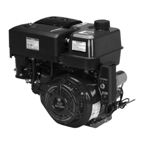
OHV GAS ENGINE - HORIZONTAL
ASSEMBLY ANd OPERATION INSTRucTIONS
IMPORTANT!
Your Warranty is voided if:
You do not put Engine oil in
the Engine's crankcase prior
to its first use.
the Engine with low or no
oil. Running the Engine with
low or no oil will permanently
damage the Engine.
Visit our website at: http://www.harborfreight.com
Read this material before using this product.
Failure to do so can result in serious injury.
SAVE THIS MANuAL.
©
Copyright
2008 by Harbor Freight Tools
contained herein may be reproduced in any shape or form without the express written consent of Harbor
Freight Tools. Diagrams within this manual may not be drawn proportionally. Due to continuing improvements,
actual product may differ slightly from the product described herein.
For technical questions or replacement parts, please call 1-800-444-3353.
Revised Manual 10e
66524-11 HP
Model
66525-13 HP
Never run
®
. All rights reserved. No portion of this manual or any artwork
Advertisement
Table of Contents

Subscribe to Our Youtube Channel
Related Manuals for Greyhound 66524-11 HP


Summary of Contents for Greyhound 66524-11 HP
- Page 1 OHV GAS ENGINE - HORIZONTAL 66524-11 HP Model 66525-13 HP ASSEMBLY ANd OPERATION INSTRucTIONS IMPORTANT! Your Warranty is voided if: You do not put Engine oil in the Engine’s crankcase prior to its first use. Never run the Engine with low or no oil.
-
Page 2: Specifications
SPEcIFIcATIONS Model 66525 Model 66524 13 HP, 4-Stroke Gasoline Engine 11 HP, 4-Stroke Gasoline Engine Air Cooled, Horizontal Shaft Air Cooled, Horizontal Shaft Electric Start w/Recoil Back-Up Electric Start w/Recoil Back-Up Engine Type Powered w/mid-to-high octane Powered w/mid-to-high octane unleaded gasoline unleaded gasoline Model: 188FD-E Model: 182FD-E... -
Page 3: General Safety Rules
SAVE THIS MANuAL work area from debris such as chips and sparks. Provide barriers or Keep this manual for the safety warnings shields as needed. Children should and precautions, assembly, operating, inspection, never be allowed in the work area. maintenance and cleaning procedures. Write the product’s serial number in the back of the manual PERSONAL SAFETY near the assembly diagram (or month and year of... -
Page 4: Specific Safety Rules
Engine and do not use the Engine for unqualified personnel could result in a purpose for which it is not intended. a risk of injury. Do not use the Engine if the Engine’s When servicing the Engine, use Ignition Switch does not turn it on or only identical replacement parts. -
Page 5: Mechanical Precautions
or pacemaker failure. Caution is When spills of fuel or oil occur, they necessary when near the Engine’s must be cleaned up immediately. magneto or recoil starter. Dispose of fluids and cleaning materials as per any local, state, or Never leave the Engine unattended federal codes and regulations. -
Page 6: Chemical Precautions
cHEMIcAL PREcAuTIONS ASSEMBLY INSTRucTIONS Avoid contact with hot fuel, oil, TO MOuNT THE ENGINE exhaust fumes, and solid surfaces. IMPORTANT: If you have any doubts Avoid body contact with fuels, oils, about your ability to perform the and lubricants used in the Engine. If following assembly procedures, you swallowed, seek immediate medical should have a qualified technician... - Page 7 ENGINE MOuNTING dIAGRAM NOT TO SCALE FACE 5” BASE 1/2” 7-11/16” 8-3/4” REV 10d For technical questions, please call 1-800-444-3353. Page 7 SKU 66524-66525...
- Page 8 PRE-OPERATING cAuTION! check to make sure the Bolts, Washers, Lock Washers, INSTRucTIONS and the Nuts used dO NOT come in contact with any moving part of Make sure the Engine’s crankcase the Engine and power equipment is filled with approximately 37 unit.
-
Page 9: Operating Instructions
screw the Fuel Filler Cap back onto the Ignition Key (19 - page 27) and the Fuel Tank. (See Figure c.) turn the Engine Ignition Switch (8 - page 27) to its “START” position. If necessary, repeat this procedure until OPERATING INSTRucTIONS the Engine starts. - Page 10 Turning the Fuel Lever to its “cLOSEd” position. Removing the Spark Plug Cap (4 - page 25). REV 09i For technical questions, please call 1-800-444-3353. Page 10 SKU 66524-66525...
-
Page 11: Inspection, Maintenance, And Cleaning Schedule
INSPEcTION, MAINTENANcE, ANd cLEANING ScHEduLE WARNING! Never perform any services or maintenance on the Engine while it is running. Before performing any inspection, maintenance, and cleaning, turn off the Engine and disconnect the Spark Plug Wire from the Spark Plug to prevent acci- dental starting. -
Page 12: Troubleshooting
Troubleshooting Problem Possible cause Possible Solution Engine will not ow on fuel or oil. dd fuel or oil. start Ignition switch is in “OFF” position. Turn ignition switch to “ON” position. Faulty spark plug. Clean or replace spark plug. Choke in wrong position. Properly adjust choke. - Page 13 PARTS LIST/dIAGRAM - cRANKcASE PART dEScRIPTION PART dEScRIPTION Washer Regulating Sway Bar Drain Plug Nut (M10) Oil Seal, Crankshaft O-Ring Seal Bolt (M6x14) Diode Oil Sensor Crankcase Carbon Irrigation Oil Seal, Regulating Sway Bar Bracket Washer Carbon Irrigation Connector Split Bin Fuel Pipe IMPORTANT When ordering parts from the above Parts list, make sure to specify the following:...
- Page 14 PARTS LIST/dIAGRAM - cRANKcASE cOVER PART dEScRIPTION PART dEScRIPTION Oil Plug with Seal Washer Oil Plug Sliding Sleeve Seal Gasket, Crankcase Crankcase Cover Set Pin (8x12) Washer, Drive Gear Dipstick Drive Gear, Regulator Dipstick with Seal Bearing (6206) Regulating Shaft Oil Seal, Crankshaft Flying Block Bolt (M8x40)
- Page 15 PARTS LIST/dIAGRAM - cYLINdER HEAd/cYLINdER HEAd cOVER PART dEScRIPTION PART dEScRIPTION Bolt Lead Wind Cover Washer Stud (M6x8x134.5) Rubber Seal Gasket, Cylinder Head Bolt Set Pin Cylinder Head Cover Assy Cylinder Head Assy. Gasket, Cylinder Head Cover Spark Plug (F7RTCU) Bolt Stud (M8x48.5) Circlip...
- Page 16 PARTS LIST/dIAGRAM - cRANKSHAFT, PISTON, cONNEcTING ROd PART dEScRIPTION PART dEScRIPTION Piston Ring (l) Bearing (6202) Piston Ring (ll) Balancing Shaft Side Rail Bearing (6207) Expander Woodruff Key Scraper Ring Set Crankshaft Piston Pin Circlip Drive Gear Piston Timing Gear Piston Pin Piston Ring Set Kit Shank...
- Page 17 PARTS LIST/dIAGRAM - cAMSHAFT, VALVE ROcKER PART dEScRIPTION PART dEScRIPTION Lock Nut Exhaust Valve Sleeve Intake Valve Valve Rocker Spring Retainer, Exhaust Valve Adjusting Bolt for Valve Gap Valve Spring Pusher Guide Spring Keeper Push Rods Spring Keeper Valve Tappets Extension Spring Valve Rocker Assy Camshaft Assy...
- Page 18 PARTS LIST/dIAGRAM - cARBuRETOR PART dEScRIPTION PART dEScRIPTION Inlet Gasket Choke Stem Connecting Block Airproof Washer Carburetor Gasket Throttle Lever Idle Adjustment Screw Washer Mixture Chamber Body Screw (M4) Main Nozzle Cover Main Jet Choke Switch Float Throttle Unit Float Chamber Gasket Spring, Mixture Adjustment Screw Float Chamber Mixture Adjustment Screw...
- Page 19 PARTS LIST/dIAGRAM - FuEL TANK PART dEScRIPTION PART dEScRIPTION Pipe Filter Cup Outlet Pipe Fuel Tank Pipe Clamp Packing Ring Connector Fuel Filler Cap Bolt (M8x25) Fuel Filler Cap w/Packing Ring Packing Ring Plug-in board Nut (M8) Bolt IMPORTANT When ordering parts from the above Parts list, make sure to specify the following: The MOdEL NuMBER (either 66525 or 66524) of the Engine for which you are ordering.
- Page 20 PARTS LIST/dIAGRAM - AIR cLEANER PART dEScRIPTION PART dEScRIPTION Wing Nut Sleeve B Air Cleaner Cover Bolt (M6x22) Filler Element Washer Air Cleaner Base Nut (M6) Sleeve A Air Cleaner Assy Air Cleaner Housing IMPORTANT When ordering parts from the above Parts list, make sure to specify the following: The MOdEL NuMBER (either 66525 or 66524) of the Engine for which you are ordering.
- Page 21 PARTS LIST/dIAGRAM - MuFFLER PART dEScRIPTION PART dEScRIPTION Nut (M8) Muffler Exhaust Pipe Gasket Screw (M5x8) Exhaust Pipe Muffler Hood Assy Muffler Gasket Muffler Assy IMPORTANT When ordering parts from the above Parts list, make sure to specify the following: The MOdEL NuMBER (either 66525 or 66524) of the Engine for which you are ordering.
- Page 22 PARTS LIST/dIAGRAM - REcOIL STARTER PART dEScRIPTION PART dEScRIPTION Engine Switch Ratchet Spring Wire Grommet Ratchet Clip Friction Spring Plastic Clip Set Screw Bolt (M6x12) Spring Lid Fan Hood Assy Rope Bolt (M6x8) Handle Casing Recoil Starter Coil Leaf Spring Recoil Starter Assy Cord Spool IMPORTANT...
- Page 23 PARTS LIST/dIAGRAM - REGuLATING cONTROL SYSTEM PART dEScRIPTION PART dEScRIPTION Bolt (M5x35) Nut (M6) Regulating Spring Spring Clamp Back Spring Bolt (M6x12) Lock Bolt Support Panel Regulating Arm Washer Regulating Arm Spring Throttle Pulling Rod Spring Patch Regulating Frame Assy Setting Panel IMPORTANT When ordering parts from the above Parts list, make sure to specify the following:...
- Page 24 PARTS LIST/dIAGRAM - FLYWHEEL PART dEScRIPTION PART dEScRIPTION Nut (M16x1.5) Flywheel Fan Starting Flange Flywheel IMPORTANT When ordering parts from the above Parts list, make sure to specify the following: The MOdEL NuMBER (either 66525 or 66524) of the Engine for which you are ordering. The PART NuMBER listed to the left of the part description.
- Page 25 PARTS LIST/dIAGRAM - IGNITION cOIL PART dEScRIPTION PART dEScRIPTION Screw (M6x30) Charge Coil Engine Stop Cable Clamp, Cord Ignition Coil Bolt (M6x35) Spark Plug Cap Bolt (M6x12) Ignition Coil Assy IMPORTANT When ordering parts from the above Parts list, make sure to specify the following: The MOdEL NuMBER (either 66525 or 66524) of the Engine for which you are ordering.
- Page 26 PARTS LIST/dIAGRAM - STARTER MOTOR PART dEScRIPTION PART dEScRIPTION Relay, Start-Up Cable, Starter Motor Rotor Comp. Insulator Starting Clutch Bolt (M5x14) Starter Motor Assy Screw (M4x6) Base, Starter Packing Ring Housing, Starter Clutch Screw (M5x32) Drive Gear Nut (M6) Brush, Comp. Bolt (M6x35) Stator Assy Spring Washer (4mm)
- Page 27 PARTS LIST/dIAGRAM - STARTER & cONTROL BOX PART dEScRIPTION PART dEScRIPTION Clamp Ring Control Rear Cover Gasket Attachment Bolt Bolt (M4x10) Protector Control Front Cover Fixed Mount Diode Spring Nut (M4) Cover Fixed Mount Protector Assy Ignition Switch Bolt (M3x12) Safety Ignition Key Diode Assy...
-
Page 28: Please Read The Following Carefully
WIRING dIAGRAM PLEASE REAd THE FOLLOWING cAREFuLLY THE MANUFACTURER AND/OR DISTRIBUTOR HAS PROVIDED THE PARTS LIST AND ASSEMBLy DIAGRAM IN THIS MANUAL AS A REFERENCE TOOL ONLy. NEITHER THE MANUFACTURER OR DISTRIBUTOR MAKES ANy REPRESENTATION OR WARRANTy OF ANy KIND TO THE BUyER THAT HE OR SHE IS qUALIFIED TO MAKE ANy REPAIRS TO THE PRODUCT, OR THAT HE OR SHE IS qUALIFIED TO REPLACE ANy PARTS OF THE PRODUCT. -
Page 29: Emission Control System Warranty
EMISSION cONTROL engine is defective, the part will be repaired or replaced by HFT. SYSTEM WARRANTY Owner’s Warranty Responsibilities california and united States Emission • As the engine owner, you are responsible control defects Warranty Statement for the performance of the required The California Air Resources Board maintenance listed in your Owner’s ( h e r e i n C A R B ) , t h e U n i t e d S t a t e s... - Page 30 No charge Repair or Replacement Service and Maintenance Repair or replacement of any warranted C o m p o n e n t p a r t s w h ic h a re n o t part will be performed at no charge to the scheduled for replacement as required owner if the work is performed through a maintenance or are scheduled only...
-
Page 31: Limited 90-Day Warranty
LIMITEd 90 dAY WARRANTY Harbor Freight Tools Co. makes every effort to assure that its products meet high quality and durability standards, and warrants to the original purchaser that this product is free from defects in materials and workmanship for the period of 90 days from the date of purchase.
Need help?
Do you have a question about the 66524-11 HP and is the answer not in the manual?
Questions and answers