
Related Manuals for AeroVironment TurboCord


Summary of Contents for AeroVironment TurboCord
-
Page 1: User Guide
USER GUIDE TURBOCORD PORTABLE CHARGER 120V/240V: DUAL VOLTAGE AeroVironment EV Solutions™... - Page 2 Dual voltage charger may be branded under different names. No portion of these materials may be duplicated, used or disclosed without prior written permission from AeroVironment, Inc. Disclaimer: This user guide includes the latest information available at the time of printing. AeroVironment, Inc. reserves the right to make changes to this user guide and/or product without further notice.
-
Page 3: Customer Support
OWNER’S RECORD model: TurboCord Dual Voltage Charger serial number (s/n): purchase date: A NOTE ON CUSTOMER SUPPORT To ensure superior service, please take note of your Serial Number when contacting AeroVironment Customer Support. Write down the Serial Number of your charger in the “Owner’s Record” above. -
Page 4: Table Of Contents
SAVE THESE INSTRUCTIONS! This manual contains important instructions for the TurboCord Dual Voltage Charger that shall be followed during installation, operation and maintenance of the unit. TABLE OF CONTENTS SECTION 1: INTRODUCTION ...........1 Symbol Usage .................2 About Your TurboCord Charger ...........3 TurboCord Charger Components ..........5... -
Page 5: Section 1: Introduction
SECTION 1 INTRODUCTION... -
Page 6: Symbol Usage
SYMBOL USAGE DANGER Indicates information about safety practices which, if not followed, may result in serious injury or death....................Indicates information about safety practices which, if not followed, could result in personal injury or are necessary WARNING to prevent fire or equipment overheating.................... -
Page 7: About Your Turbocord Charger
ABOUT YOUR TURBOCORD CHARGER Thank you for purchasing the AeroVironment™ (AV) TurboCord Dual Voltage Charger – our easy-to-use, compact, and portable power supply for your electric vehicle’s on-board charger. The charger supplies and manages AC power to your electric vehicle and is compatible with a variety of battery electric and plug-in hybrid electric vehicles. - Page 8 • Do not use in a commercial garage classified for internal combustion engine vehicles due to vapors of flammable liquids (gasoline) being present. TurboCord will not charge and will give a fault indication if NOTE ground is not present.
-
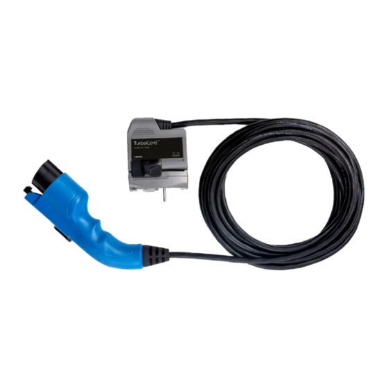
Page 9: Turbocord Charger Components
TURBOCORD CHARGER COMPONENTS 240 V ADAPTER CLIP 240 V ADAPTER CHARGE MODULE Release button CHARGE COUPLER... -
Page 10: Required Outlets
REQUIRED OUTLETS NOTE Any electrical socket should be checked by an electrician. 120 VAC operation: a NEMA 5-15R wall outlet is required. NEMA 5-15R receptacle 120 V A dedicated 120 VAC single phase circuit and a 15-amp NOTE rated circuit breaker are required. 208/240 VAC operation: a NEMA 6-20R wall outlet is required. -
Page 11: Section 2: Using Your Dual Voltage Charger
SECTION 2 USING YOUR TURBOCORD CHARGER... -
Page 12: Know Your Indicator Lights
KNOW YOUR INDICATOR LIGHTS The indicator light on your dual voltage charger is the first thing you will notice when you are about to plug or unplug your vehicle. Before we get started, here is a simple explanation of the indicators. CHARGE MODULE INDICATOR LIGHTS Red TROUBLE Blue STATUS... -
Page 13: Charging Your Vehicle
CHARGING YOUR VEHICLE Your charger is designed for easy charging in two modes – 120 VAC and 240 VAC. 120 VAC MODE When used WITHOUT the ADAPTER, the charger connects to a 120 V outlet and charges your vehicle in “Level 1” charging mode. The Level 1, 120 VAC charge regimen takes longer to charge than the Level 2, 240 VAC mode;... -
Page 14: 240 Vac Mode
240 VAC MODE When used WITH the ADAPTER, the charger can charge in Level 2, 240 VAC mode. ← ← Charge Module Adapter Clip Adapter Snap the ADAPTER CLIP to the lower end of the CHARGE MODULE, lining up the appropriate symbols ( ) on the clip and module. -
Page 15: Manual Stop
When plugging into an unfamiliar wall outlet, it is good practice to let the vehicle charge for several minutes before leaving it unattended, to ensure it is in fact supplying the expected AC charging power. NOTE The RED TROUBLE Indicator will illuminate if not charging. The unit will turn OFF if breaker or infrastructure GFI is tripped. - Page 16 CHAPTER 3 TROUBLE SHOOTING...
-
Page 17: Section 3: Troubleshooting
TROUBLESHOOTING Please refer to this Troubleshooting Guide for possible solutions to common errors or difficulties with charging your vehicle using your portable charger. Do not attempt to repair or service the charger yourself. NOTE There are no user serviceable parts inside. A RED TROUBLE Indicator may be triggered by several sources, including the charger, the utility service, or the vehicle. - Page 18 Problem Possible Cause Solution RED TROUBLE Utility fault 1. Disconnect the charger module from the wall outlet, Indicator is blinking then reconnect to the wall rapidly outlet. 2. If the condition persists, have a qualified electrician inspect the wall outlet ground circuit integrity.
-
Page 19: Appendix
APPENDIX... -
Page 20: Specifications
SPECIFICATIONS Model Dual voltage 120 VAC Line input power: 240/208 VAC 12 amps continuous @ 120 VAC Output power: 16 amps continuous @ 240/208 VAC 15 amps @ 120 VAC Circuit breaker rating: 20 amps @ 240 VAC Frequency: 60 Hz Power draw at idle <... -
Page 21: Installing The Cable Hanger
INSTALLING THE CABLE HANGER CABLE HANGER MOUNTING INSTRUCTION 1. Choose a location to install the cable hanger. The hanger should be located in practical proximity to both the utility • service and the location of your vehicle’s charge receptacle. Preferably mounted to a wall stud. -
Page 22: High Voltage Warning
HIGH VOLTAGE WARNING High voltage is present in your electric meter housing DANGER and power distribution service panel. Contact with high voltage can cause death or serious personal injury....................DO NOT operate your charger with a damaged output cable, charge coupler, adapter, or module. Visually inspect the output cable, charge coupler, adapter, and WARNING charger module for damage before each use. -
Page 23: State Of California Proposition 65 Warnings
STATE OF CALIFORNIA PROPOSITION 65 WARNINGS This product contains a chemical known to the State WARNING of California to cause cancer or birth defects or other reproductive harm. FCC INFORMATION This device complies with Part 15 of the FCC Rules. Operation is subject to the following two conditions: • This device may not cause harmful interference. - Page 24 GFCI Protection: The charger is equipped with a Ground Fault Circuit • Interruption (GFCI) reaction system to protect against electric shock. If the charger module detects an output ground fault, it will shut down power to the output cable and illuminate the RED TROUBLE Indicator. Insulation: The charger module, adapter, cable assembly and charge •...
-
Page 25: Warranty
TURBOCORD CHARGER LIMITED WARRANTY KEEP RECEIPT FOR WARRANTY CLAIMS. The AeroVironment, Inc. (AV) TurboCord EV charger is warranted to be free of defects in material and workmanship for a period of thirty-six (36) months from the date of original purchase. -
Page 26: Index
INDEX adapter ..3, 5, 10, 13, 14, manual stop ...... 11 16, 18, 20 adapter clip ....5, 10 auto-restart ....... 11 outlet ...... 3, 4, 6, 8, 9, 10, 11, 13, 14 output ground ....20 BLUE STATUS indicator ..8, 9, 10, 11, 13, 14 pilot signal wire .... - Page 28 AeroVironment EV Solutions Customer Support 1-888-833-2148 evscs@avinc.com Corporate Headquarters AeroVironment, Inc. EV Solutions™ 181 W. Huntington Drive, Suite 202 Monrovia, CA 91016 Corporate phone: 626-357-9983 or 888-833-2148 ev@avinc.com www.evsolutions.com 22600-03 Rev 1...
Need help?
Do you have a question about the TurboCord and is the answer not in the manual?
Questions and answers