Sony UWP-C1 Operating Instructions Manual
Wireless microphone package
Hide thumbs
Also See for UWP-C1:
- Operating instructions manual (64 pages) ,
- Specification sheet (12 pages) ,
- Brochure & specs (8 pages)

Related Manuals for Sony UWP-C1


Summary of Contents for Sony UWP-C1
- Page 1 2-347-711-32(2) Wireless Microphone Package Operating Instructions Before operating the unit, please read this manual thoroughly and retain it for future reference. UWP-C1/C2 UWP-S1/S2 UWP-X1/X2 2003 Sony Corporation...
-
Page 3: Table Of Contents
Table of Contents Setting the reception channel ... 29 Configuration of the Detecting and selecting the Packages ......4 available channels UWP-C1 ........4 automatically (diversity tuner UWP-C2 ........5 module (URX-M1) only) ..30 UWP-S1 ........6 Setting the attenuation level UWP-S2 ........ -
Page 4: Configuration Of The Packages
UWP-C1 The UWP-C1 consists of a body-pack transmitter (UTX-B1) and a portable diversity tuner (URX-P1). When used in conjunction with a compact camcorder, the UWP-C1 makes a mobile system for ENG (Electronic News Gathering) or EFP (Electronic Field Production) purposes. -
Page 5: Uwp-C2
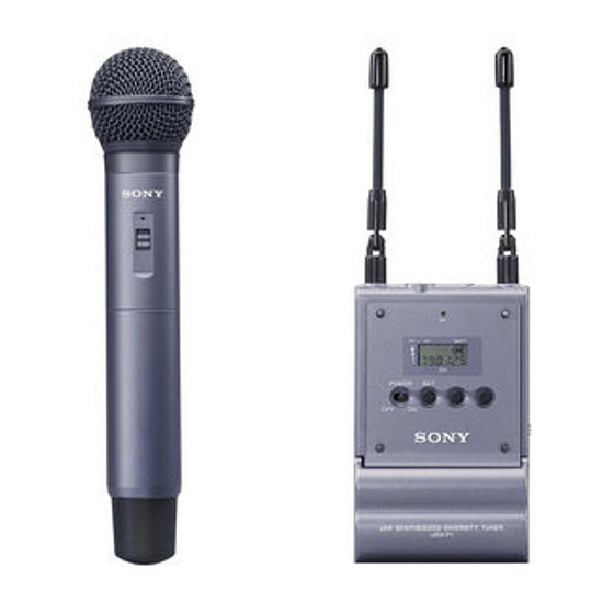
UWP-C2 The UWP-C2 consists of a hand-held microphone (UTX-H1) and a portable diversity tuner (URX-P1). When used in conjunction with a compact camcorder, the UWP-C2 makes a mobile system for ENG (Electronic News Gathering) or EFP (Electronic Field Production) purposes. Hand-held microphone Portable diversity tuner (UTX-H1) (1) -
Page 6: Uwp-S1
Configuration of the Packages UWP-S1 The UWP-S1 consists of a body-pack transmitter (UTX-B1) and a half-rack size diversity tuner (URX-R1). The UWP-S1 is suitable for constructing a wireless system for AV presentations. Body-pack transmitter Half-rack size diversity tuner (UTX-B1) (1) (URX-R1) (1) Supplied accessories •... -
Page 7: Uwp-S2
UWP-S2 The UWP-S2 consists of a hand-held microphone (UTX-H1) and a half-rack size diversity tuner (URX-R1). The UWP-S2 is suitable for constructing a wireless system for AV presentations. Hand-held microphone Half-rack size diversity tuner (UTX-H1) (1) (URX-R1) (1) Supplied accessories •... -
Page 8: Uwp-X1
Configuration of the Packages UWP-X1 The UWP-X1 consists of a body-pack transmitter (UTX-B1) and a diversity tuner module (URX-M1). By installing the tuner module into a tuner base unit or a powered mixer, the system construction to meet the desired purpose of use and required system scale becomes possible. -
Page 9: Uwp-X2
UWP-X2 The UWP-X2 consists of a hand-held microphone (UTX-H1) and a diversity tuner module (URX-M1) . By installing the tuner module into a tuner base unit or a powered mixer, the system construction to meet the desired purpose of use and required system scale becomes possible. -
Page 10: Features
Features Features Portable diversity tuner Each of the UWP-C1/C2/S1/S2/X1/ X2 wireless microphone packages (URX-P1) (referred to as the UWP series This tuner employs a space diversity hereafter) combines a transmitter system with little signal dropout and (body-pack transmitter (UTX-B1) or two angle-adjustable antennas. - Page 11 Half-rack size diversity tuner UWP-X2 (URX-R1) This tuner employs a space diversity Hand-held microphone (UTX-H1) system with little signal dropout and This microphone is equipped with a two angle-adjustable antennas. It built-in antenna and a unidirectional comes with two types of audio dynamic microphone unit.
-
Page 12: Precautions
Precautions Precautions • The UWP series product must be To prevent electromagnetic used within a temperature range of interference from portable 0°C to 40°C (32°F to 104°F). communication devices • Operating the UWP series product The use of portable telephones and near electrical equipment (motors, other communication devices near transformers, or dimmers) may cause... -
Page 13: Parts Identification
Parts Identification A AF (audio frequency) indication Body-pack transmitter Appears whenever the input audio (UTX-B1) signal is stronger than the reference level. B RF (antenna output) indication Appears during signal transmission from the antenna. C RF (antenna output) level indication Shows the RF output level setting. -
Page 14: Hand-Held Microphone (Utx-H1)
Parts Identification 5 + (+ selection) / – (– selection/ 1 Power indicator reset) buttons Lights up red when the microphone is Press these buttons to set the turned on. transmission channel, frequency, or attenuation level of the input signal. 2 POWER switch The “–”... -
Page 15: Portable Diversity Tuner (Urx-P1)
D BATT (battery) indication Portable diversity tuner Shows the battery condition. (URX-P1) For details, see “Power Supply” on page 20. E CH (channel) indication Shows the transmission channel. Each time you press the SET button, the channel indication changes as follows. For details, see “Settings”... - Page 16 Parts Identification 4 Display section 5 + (+ selection) / – (– selection/ reset) buttons Press these buttons to set the reception channel and frequency. The “–” button resets the accumulated battery BATT use time to “00:00”. These buttons can also be used to adjust the monitor level.
-
Page 17: Half-Rack Size Diversity Tuner (Urx-R1)
4 MONITOR control Half-rack size diversity Turn to adjust the output monitoring tuner (URX-R1) level (through the headphones). 5 + (+ selection) / – (– selection/ Front panel reset) buttons Press these buttons to set the reception channel and frequency. 6 Display section Rear panel A RF (radio frequency) indications... -
Page 18: Diversity Tuner Module (Urx-M1)
Parts Identification qs DC IN 9V (DC power input) Reception connector channel Press group and Connect the supplied AC adapter here. number button. Reception Diversity tuner module frequency (URX-M1) 7 RF (radio frequency) indicator Indicates the strength of the RF input signal. - Page 19 A RF (radio frequency) indications The number of dots indicates the RF input level. B AF (audio frequency) indication Appears whenever the output audio signal is stronger than the reference level. C GP (group)/CH (channel) indication Shows the reception channel group and channel number.
-
Page 20: Power Supply
Power Supply Power Supply This section explains the power supply Inserting the batteries for each component. Body-pack transmitter (UTX- • Half-rack size diversity tuner (URX-R1) B1)/portable diversity tuner Connect the supplied AC adapter to (URX-P1) the DC IN 9V connector on the rear The procedure below uses the body- panel, and then connect the AC pack transmitter (UTX-B1) in the... - Page 21 Hand-held microphone (UTX-H1) Turn the grip in the direction of the arrow to open the battery compartment. Turn the grip in the direction opposite to the arrow in step 1 to close the battery compartment. Note Align two new LR6 (size AA) If you open the battery compartment alkaline batteries with the polarity during signal transmission, the noise...
- Page 22 If the batteries do leak, clean all leakage from the battery compartment and the component. Leakage left in the compartment and the component may cause poor battery contact. If there seems to be poor battery contact, consult your Sony dealer.
-
Page 23: Attachment And Installation Procedures
Attachment and Installation Procedures This section describes the procedures Attaching the wind screen to for attaching the supplied accessories the microphone to components and the installation of the diversity tuner module (URX-M1) into the MB-806A Tuner Base Unit or SRP-X700P Powered Mixer. Attaching the supplied Insert the microphone into the hole at the bottom of the windscreen. -
Page 24: Attaching The Supplied Accessory To The Hand-Held Microphone (Utx-H1)
Attachment and Installation Procedures Removing the belt clip Attaching the supplied Insert a pointed object such as a accessories to the ballpoint pen between the belt clip and portable diversity tuner the transmitter to make some space (URX-P1) between them, and then remove the end of the belt clip from the hole on the side of the transmitter. -
Page 25: Installing The Diversity Tuner Module (Urx-M1)
Attaching the shoe mount Attaching the microphone adapter stand adapter After attaching the belt clip and the shoe mount adapter, insert the microphone stand adapter into the screw hole at the top of the shoe mount adapter, and then rotate the microphone stand adapter until it is securely attached. - Page 26 Attachment and Installation Procedures • The buttons and display on the front To install two or more diversity panel of the diversity tuner module tuner modules (URX-M1) , detach (URX-M1) may be damaged if they the necessary number of blank are gripped too strongly.
- Page 27 Installing a diversity tuner module (URX-M1) into an SRP-X700P Powered Mixer The SRP-X700P Powered Mixer can accommodate up to 2 diversity tuner Diversity tuner modules (URX-M1). module (URX-M1) Remove the tuner slot cover from the SRP-X700P and inspect the top and bottom sides of the diversity tuner module.
-
Page 28: Settings
Settings Settings When the desired channel number Setting the (or frequency) appears, set the transmission channel POWER switch to OFF to complete the setting, or press the The procedure below is the SET button to set other items. same for all UWP series transmitters (UTX-B1/H1). -
Page 29: Setting The Reception Channel
Hold down the + or – button to Setting the reception change the channel group faster. channel When the desired channel group The procedure below is the number appears, press the SET same for all UWP series tuners button. (URX-P1/R1/M1). The selected group is entered. -
Page 30: Detecting And Selecting The Available Channels
Settings • If you turn off the tuner and then To selct the channel by immediately turn it on right after frequency indication setting the reception channel, the unit may not operate normally. Wait a Press the SET button for more few seconds before turning it on than one second. -
Page 31: Setting The Attenuation Level Of The Audio Input
Do the following while there All the tuner modules installed is no signal transmission. into the MB-806 are set to the available channels within the Turn on the transmitter while selected channel group. pressing down the SET button, and press the SET button After the automatic detection and selection of available channels repeatedly until the attenuation... -
Page 32: Resetting The Accumulated Battery Use Time Indication
Settings Press the – button. Resetting the accumulated battery The time indication resets to use time indication “00:00.” While “00:00” is still displayed, The procedure below is the you can return to previous value same for all UWP series by pressing the + button. transmitters (UTX-B1/H1) and the portable diversity tuner For transmitters (UTX-B1/H1) -
Page 33: Setting The Monitor Level (Portable Diversity Tuner (Urx-P1) Only)
Press the SET button repeatedly Press the + button to increase the until the RF output level monitor level, or press the – indication appears in the display button to decrease the level. section. When you leave the tuner for about two seconds or more, current monitor level setting is stored in memory and the normal... -
Page 34: Operation
Operation Operation The procedure below is the If noise is heard same for all UWP series components (UTX-B1/H1 and Depending on the environment where URX-P1/R1/M1). the UWP series components are installed, external noise or radio Make all necessary connections waves may disrupt transmission on on the tuner. -
Page 35: System Configurations
System Configurations The UWP series is used in the following configuration examples. Sample configurations for ENG (Electronic News Gathering) or EFP (Electronic Field Production) with a digital camcorder Portable diversity tuner (URX-P1) (with the shoe mount adapter attached) DSR-PDX10/PDX10P/PD150/PD150P DVCAM Digital Camcorder Body-pack transmitter (UTX-B1) Portable diversity tuner... - Page 36 System Configurations Sample configurations for AV presentations Portable diversity tuner (URX-P1) (with the shoe mount adapter attached) Hand-held microphone (UTX-H1) Body-pack transmitter (UTX-B1) To DVD player, PC, or VTR, etc. SRP-X700P Powered Mixer Hand-held Half-rack size diversity microphone tuner (URX-R1) (UTX-H1) To DVD player, PC, or VTR, etc.
- Page 37 Sample configuration of a PA system Hand-held microphone (UTX-H1) AN-820 UHF antenna Diversity tuner module (URX-M1) Body-pack transmitter (UTX-B1) To DVD player, PC, or VTR, etc. SRP-X700P Powered Mixer 1 Lavalier microphone (supplied) Diversity tuner 2 BNC cable module (URX-M1) 3 XLR cable 4 XLR cable or pin cable *1 WD-820A Antenna Divider...
-
Page 38: Error Messages
When a problem occurs, one of the following error messages may appear on the display. Messages Meanings Remedy Err 01 An error has occurred in the backup memory Contact your Sony dealer. data. Err 02 The PLL synthesized circuit is abnormal. Restart the unit. If the message appears again, contact your Sony dealer. -
Page 39: Troubleshooting
Troubleshooting If you have any problem using the UWP system, use the following checklist. Should any problem persist, consult your Sony dealer. Symptom Meanings/Remedy The unit does not turn on The polarity orientation of the batteries in the battery compartment is incorrect. b Insert the batteries with the correct polarity orientation. - Page 40 Troubleshooting Symptom Meanings/Remedy There is distortion in the sound. The attenuation level of the transmitter is too low. b The input level of the tuner is extremely high. Press the – button on the transmitter in attenuation level setting mode to raise the attenuation level. The transmitter and the tuner are set to different channels.
-
Page 41: Specifications
Specifications Body-pack transmitter Transmitters (UTX-B1/ (UTX-B1) Antenna 1/4λ (wave length) wire Items common to all Audio input connector 3.5-mm dia. mini jack transmitters Audio input level Oscillator type –60 dBV to –39 dBV Crystal-controlled PLL Dimensions synthesizer Carrier frequencies 794 to 806 MHz Operating frequency band 12 MHz RF output level... - Page 42 Specifications Hand-held microphone Tuners (URX-P1/R1/M1) (UTX-H1) Items common to all tuners Microphone unit Dynamic Type of reception Directivity Space diversity Unidirectional Oscillator type Antenna 1/4λ (wave length) wire Crystal-controlled PLL (internal) synthesizer Dimensions Reception frequencies 794 to 806 MHz Operating frequency band 12 MHz Signal-to-noise ratio 60 dB or more...
- Page 43 Display Channel, frequency, audio Half-rack size diversity tuner level, RF level, (URX-R1) accumulated battery use time, monitor level Antenna 1/4λ (wave length) wire (adjustable angle) Power requirements Squelch level 3.0 V DC (two LR6/AA- size alkaline batteries) 25 dBµ Balanced audio output level Battery life –28 dBm (LINE level)/–58 Approx.
- Page 44 Specifications Mass Approx. 1.3 kg (2 lb 14 oz) Diversity tuner module (URX- Squelch level 25 dBµ Display Channel, frequency Dimensions 57 × 26 × 121 mm (2 × 1 × 4 inches) (w/h/d) Mass Approx. 150 g (5 oz) Design and specifications are subject to change without notice.
-
Page 45: Appendix
Instruction Manual of your unit. Guidance on the use of a multi-channel system When building up a multi-channel system, Sony recommends that one of the groups listed under “Groups for the tuner” is selected to avoid mutual interference from other Sony wireless microphones/transmitters. - Page 46 Appendix Groups for tuner Group 11 Group 12 Group 13 Grouping 11 channels. Grouping 8 channels. Grouping 8 channels. 69-01 800.125 68-03 794.375 68-05 794.625 69-05 800.625 68-13 795.625 68-14 795.750 69-11 801.375 68-18 796.250 68-25 797.125 69-25 803.125 68-26 797.250 68-41 799.125...
-
Page 47: Ac Adapter For Use With The Urx-R1
AC adapter for use with the URX-R1 Please prepare an AC adapter which satisfies the following conditions for normal operation of the URX-R1 Half-rack Size Diversity Tuner. • Specifications AC input voltage: Differs according to the countries. DC output voltage: 9.0 V DC Rated load current: more than 300 mA DC •... - Page 48 Sony Corporation Printed in Korea...
Need help?
Do you have a question about the UWP-C1 and is the answer not in the manual?
Questions and answers