Table of Contents
Advertisement
Advertisement
Table of Contents

Subscribe to Our Youtube Channel
Related Manuals for Topcon RC-2W


Summary of Contents for Topcon RC-2W
- Page 1 INSTRUCTION MANUAL REMOTE CONTROL SYSTEM 2W RC-2W...
-
Page 3: Foreword
Foreword Foreword Thank you for purchasing the Topcon RC-2W Remote control system-2W. For the best performance of the instrument, please read these brief instructions carefully, and keep them in a convenient location for future reference. This system has the following features: ●... -
Page 4: Safety Information
• There is a risk of fire, electric shock or physical harm if you attempt to disassemble or repair the instrument yourself. This is only to be carried out by TOPCON or an authorized dealer, only! • Risk of fire or electric shock Do not use damaged power cable, plug and socket. -
Page 5: User
As per the said standard, this product is classified as “Class 1 (I) Laser Products”. This is simple a product to operating that is not required to training from a “Laser safety officer”. In case of any failure, do not disassemble the instrument. Contact TOPCON or your TOPCON dealer. -
Page 6: Table Of Contents
Installing RC-2RW onto the DM pole..........9 Communication between the RC-2W and a data collector ......10 Mounting remote controller handle unit RC-2H onto the total station . -
Page 7: Standard System Components
Foreword Standard System Components Remote controller RC-2RW ......1pc. Remote controller Handle unit RC-2H . -
Page 8: Nomenclature And Functions
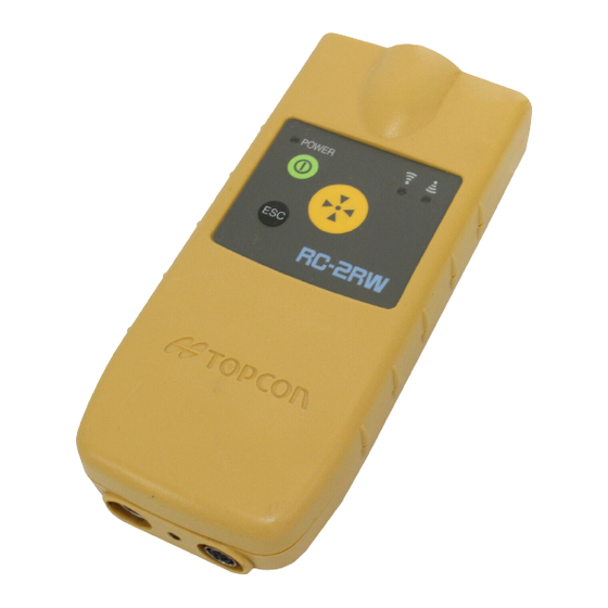
Nomenclature and Functions Nomenclature and Functions Remote Controller RC-2RW Emitting window (Laser beam aperture) Operating keys Receiving window Prism unit A3/A3S (Optional accessory) DM pole RC-2RW Holder RC-2B for prism unit A3/A3S RC-2RW fixing screw Rear side Bottom Hook for holder Connector for holder RC-2B (When using Bluetooth Serial signal... -
Page 9: Remote Controller Handle Unit Rc-2H
Nomenclature and Functions Panel Turn-round key Power LED Receiving LED Power switch Sending LED Escape key Function Power switch ON/OFF of power of the RC-2RW. Turn-round motion key Total station will be in turn-round motion. Cancels the emitting laser for turn-round motion. The total station will stop Escape key the turn-round operation after continuing the motion for a while. -
Page 10: Preparation
Preparation Preparation Battery installation and replacement Push up the battery cover unhooking Battery cover Lugs lever and detach the cover. Install four new “AA” size dry cells with correct polar orientation as shown on the side of the battery housing. Insert the top lugs of battery cover and press the cover until it is snapped shut. -
Page 11: Installing Rc-2Rw Onto The Dm Pole
Preparation Installing RC-2RW onto the DM pole RC-2RW can be installed onto the DM pole as shown below:. Insert the DM pole into the holder and secure the holder by fastening the pole fixing screw. Hook the RC-2RW to the hook of the holder and tighten the RC-2RW fixing screw of the holder. -
Page 12: Communication Between The Rc-2W And A Data Collector
Preparation Communication between the RC-2W and a data collector ● For communicating between the FC-1000 ● For communicating between the FC-1000 (or and the RC-2W by means of Bluetooth, another data collector) and the RC-2W by connect the RC-2B’s connector to the means of an RS-232C connector, connect the RC-2RW. -
Page 13: Basic Operation
Basic Operation Basic Operation Power switch ON Press the power switch. Power LED will light. Power switch Power LED Battery Remaining Display for RC-2RW When the battery of the RC-2RW is low, the power LED will flash with beep sound. (Audio sound: Two pitches, frequent beep synchronized with power LED) Confirm the battery remaining when turning on the instrument. -
Page 14: Setting For Optical Communications With Total Station
Basic Operation Setting for Optical communications with total station The following settings is prerequisites for the optical communications to take place between the total station (or an application program) and RC-2RW. Setting Parameters in total station ● When communicating by using [EXT.LINK] of the application software (AP-L1 communication mode). -
Page 15: Table Of Item To Be Set
Basic Operation Table of item to be set Following parameters surrounded that you must set for RC-2RW and total station. ● Setting Parameters in total station Setting Operation Item By using "EXT.LINK" Without using "EXT.LINK" (AP-L1 communication (GTS communication mode) mode) [F1]CABLE/RADIO MODEM/RC... -
Page 16: Light Emitting Angle
Basic Operation Light emitting angle Laser beams are emitted from the light emitter of the RC-2RW. The angle of emitting laser beams is as follows. Top view Light emitting angle At greater distances, the laser light at the edge of the beam field (angle) will be weaker. -
Page 17: Light Detecting Range
Basic Operation Light detecting range The detecting angles of RC-2RW and RC-2H (Total station) are shown below: Total station can only be turned round with the turn-round key under the condition that RC-2RW remains confined within the range as shown below where RC-2H can detect light. RC-2RW should be aimed in a way to always capture the total station within this range during receiving data from the total station. -
Page 18: Turn-Round Function
Basic Operation Turn-round function ● RC-2RW should be kept aiming so that the total station always stays within the above range of laser beam emission until the turn-round motions is completed. If the aiming is out of above range while RC-2RW is in turn-round motions, the Important turn-round could not be completed. -
Page 19: Tracking Sensitivity Of Total Station
Basic Operation Tracking Sensitivity of total station (Only for GTS-800A/810A) When executing turn-around operations at separation distances of 100 m or more from the total station, the manufacturer recommends setting the tracking sensitivity of the total station to high (H) in order to make operations more consistent. On the low (L) and medium (M) settings, distance and weather conditions can increase the time required for turn-around operations, and under certain adverse conditions total station operations might even be impossible. -
Page 20: Minimum Distance For Optical Communication
Basic Operation Minimum Distance for Optical Communication If you are not using the external detector(optional accessory), attach the prism unit as close as possible to the RC-2RW. The minimum distance for optical communication is then determined by the distance between the prism and the receiving window (dP), as described below. Prism (unit A3/A3S) Minimum distance Prism position (dP) -
Page 21: Setting Mode
Setting Mode Setting Mode In this mode, following items can be set. Setting Items Items Selecting item Description Sets a channel to be used for communications. The same communication channel must be assigned to both RC- Communication 2RW and the total station. 1 to 3 channel The turn-round function will work regardless of setting... -
Page 22: System / Prism System
System / Prism System System / Prism System System RC-2H Normal handle is changed to RC-2H GTS-820A, GPT-8000A Series Prism System RC-2RW RC-2B Prism unit A3/A3S... -
Page 23: Special Accessories
Special Accessories Special Accessories Data Collector Prism unit-A3/A3S Suitable for systemization of measuring instrument. Measuring data will be automatically stored and transferred to a computer system, making measuring operations more efficient and saving time and effort in such operation. RC-2RW Holder RC-2B for prism unit A3/A3S External detector Holder for DM pole... -
Page 24: Precaution
Precaution Precaution ● Always clean the instrument after use. Remove the dust using a brush, then wipe off with a soft cloth. For cleaning the lens surface of the receiving window, use a cleaning brush, then use a clean lintless cotton cloth. Moisten it with alcohol (or mixture with ether) to wipe gently in a rotational motion from the center out. -
Page 25: Specifications
Specifications Specifications Operating temperature -20 ° C to +50 ° C Storing temperature -30 ° C to +60 ° C Protection against water RC-2RW: IP65 and dust RC-2H: IP54 (Based on the standard IEC60529) Operating distance * 1) GTS-800A/810A : 10m~250 m (33ft ~820 ft) GTS-820A/8000A : 15m~250 m (49ft ~820 ft) (When using with the prism unit A3/A3S) * 1) - Page 26 Specifications [Emitting Laser] Angle of Laser Each direction ±5 ° At greater distances, the laser light at the edge of the emitting range (angle) will be weaker by laser emitting characteristic. ±5 ° 100m (328ft): Approximately 250m (820ft): Approximately ±3 ° Laser class Class 1/ Class l [Detecting Laser]...
- Page 28 TOPCON CORPORATION BEIRUT OFFICE P. O. BOX 70-1002 Antelias, BEIRUT-LEBANON. TOPCON (GREATBRITAIN) LTD. Phone: 961-4-523525/961-4-523526 Fax: 961-4-521119 Topcon House Kennet Side, Bone Lane, Newbury, Berkshire RG14 5PX U.K. TOPCON CORPORATION DUBAI OFFICE Phone: 44-1635-551120 Fax: 44-1635-551170 survey.sales@topcon.co.uk laser.sales@topcon.co.uk C/O Atlas Medical FZCO., P. O. Box 54304, C-25, Dubai Airport Free Zone,UAE...
Need help?
Do you have a question about the RC-2W and is the answer not in the manual?
Questions and answers