Table of Contents
Advertisement
Quick Links
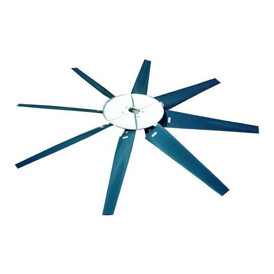
Adjustable Pitch Fan Assembly
Hudson Tuf-Lite
®
and Tuf-Lite II
Hudson Tuf-Lite
®
(black) fan blades are made from fiberglass reinforced epoxy resin having a very high
strength-to-weight ratio and corrosion resistance (not shown).
Hudson Tuf-Lite II
®
(white, prev. blue***) fan blades are made from fiberglass reinforced vinyl-ester resin
having a very high strength-to-weight ratio and superior ultra-violet and corrosion resistance. An elastomeric
blade/holder joint cover (not shown) prevents moisture from entering the blade (shown above).
The individually balanced blades can be replaced independently – matched sets are not required.
Installation Manual 5000
22' thru 30' Diameter
®
fan blades
Page 1 of 8
Tuf-Lite
Tuf-Lite II
5000 Series Hub
INSTALLATION MANUAL
®
and
®
Fans
April 2010
Advertisement
Table of Contents

Related Manuals for Hudson Tuf-Lite 5000 Series


Summary of Contents for Hudson Tuf-Lite 5000 Series
- Page 1 ® and Tuf-Lite II Hudson Tuf-Lite ® (black) fan blades are made from fiberglass reinforced epoxy resin having a very high strength-to-weight ratio and corrosion resistance (not shown). Hudson Tuf-Lite II ® (white, prev. blue***) fan blades are made from fiberglass reinforced vinyl-ester resin having a very high strength-to-weight ratio and superior ultra-violet and corrosion resistance.
- Page 2 Long T-Handle Allen Wrench Set (3/16” to 3/8”) Medium Size Flat Head Screw Driver Brass Ball Peen Hammer Flat Bastard File 240 Grit Sand Paper Anti-Seize Lubricant WD-40 12” Crescent Wrench ASSEMBLY WITH BUSHING Clean all mating surfaces between hub, bushing and shaft. All grease and lubricant should be removed, leaving the mating sur- faces dry.
-
Page 3: Blade Installation
THRUST RETAINER (optional equipment) Install proper load bolt (not provided) into top of fan shaft and tighten (See Figure 1). Install thrust retainer channel on top hub plate using existing hub spool cap screws. Torque cap screws to 60-65 ft-lb. Install thrust retainer eyebolt and jam nut. Hand tighten eyebolt. - Page 4 +/-0.2°. Fan pitch angle is shown on fan specification sheet for design duty. After desired pitch angle is set, raise and lower end of fan blade and find midpoint of blade travel. Hold blade at the midpoint. Pull blade outward so that the blade neck flange rests against the back of the blade clamps.
-
Page 5: Operating Instructions
Rotate fan in position inside fan stack to check tip clearance (See Figure 8). The recommended tip clearance is between 1” and 1 1/2 ”. Check for spots where fan blade clearance is not within the recommended tolerance. If necessary adjust fan stack by shimming to obtain proper clearance. - Page 6 Hub Spool: Ductile Iron, Zinc Rich Coating Plates: Galvanized Steel, Coal Tar Epoxy Bushing: Malleable Iron Seal Disc: Fiberglass Reinforced Polyester WHEN ORDERING, SPECIFY FAN DIAMETER, TYPE & NUMBER OF BLADES & SHAFT DIAMETER EXAMPLE: Fan Model Adjustable Pitch Installation Manual 5000...
- Page 7 Installation Manual 5000 Page 7 of 8 April 2010...
- Page 8 1-800-634-9160 (24 Hours) EMAIL: hudsonproducts@hudsonproducts.com http://www.hudsonproducts.com Hudson, Auto-Variable, Combin-Aire, Exact-A-Pitch, Fin-Fan, Heatflo, Hy-Fin, Split-Flo, Solo Aire, Stac-Flo, Steamflo, Thermflo, Tuf-Edge, Tuf-Lite, Tuf-Lite II, and Tuf-Lite III are registered trademarks of Hudson Products Corporation. ©2003 Hudson Products Corp. All Rights Reserved.
Need help?
Do you have a question about the Tuf-Lite 5000 Series and is the answer not in the manual?
Questions and answers