Table of Contents
Advertisement
Advertisement
Table of Contents

Related Manuals for Axeon Water Technologies CT-4000

Summary of Contents for Axeon Water Technologies CT-4000
-
Page 1: Reverse Osmosis
Reverse Osmosis User’s Manual Model CT-4000, CT-5000, CT-7000 CT-7000 Pictured... - Page 2 This Page Left Blank ENGF-107 REV. A 01/11 © 2011 AXEON Water Technologies...
-
Page 3: Table Of Contents
CT-5000 MEMBRANE FLOW DIAGRAM ..............21 CT-7000 MEMBRANE FLOW DIAGRAM ..............22 SYSTEM PURGING ....................23 INITIAL START-UP ....................24 DESIGN BASIS FOR CT-4000, CT-5000, CT-7000 ..........25 OPERATING DO’s & DON’Ts ..................26 OPERATION & MAINTENANCE ................26 MEMBRANE REMOVAL & REPLACEMENT ............. 29 FLUSHING THE SYSTEM .................. -
Page 4: Introduction
WARNING: INDICATES STATEMENTS THAT ARE USED TO IDENTIFY CONDITIONS OR PRACTICES THAT COULD RESULT IN INJURY OR LOSS OF LIFE. FAILURE TO FOLLOW WARNINGS COULD RESULT IN SERIOUS INJURY OR EVEN DEATH. ENGF-107 REV. A 01/11 © 2011 AXEON Water Technologies... -
Page 5: Feed Water & Operation Specifications
CT-Series reverse osmosis systems are designed to produce permeate water at the capacities indicated by the suffix in the system’s name under the conditions listed above. For example, the CT-4000 produces 4000 gallons per day of permeate water at the listed operating test conditions. -
Page 6: System Requirements & Operation Guidelines
2. Attach the inlet piping to the 1” FNPT Solenoid Valve feed water inlet. 3. Be certain that all of the components of the feed water are soluble at the concentrations attained in the system. NOTE: FEED LINE MUST BE MINIMUM 3/4” INCH. ENGF-107 REV. A 01/11 © 2011 AXEON Water Technologies... - Page 7 220/380/460 Volt, 50/60 Hertz, 1 Phase/3 phase. Each CT-Series system is equipped with a 5 foot electrical cord. Ensure that the electrical circuit supplying the system is compatible with the requirements of the specific CT model you are installing. ENGF-107 REV. A 01/11 © 2011 AXEON Water Technologies...
- Page 8 • The pump must NEVER be run dry. Operating the pump without sufficient feed water will damage the pump. • ALWAYS feed the pump with filtered water. The pump is susceptible to damage from sediment and debris. ENGF-107 REV. A 01/11 © 2011 AXEON Water Technologies...
-
Page 9: Membrane Elements
CT-Series reverse osmosis systems come pre-loaded with Thin Film Composite (TFC) HF1 High Flow Low Energy membranes, unless otherwise specified. General membrane element performance characteristics are listed on the next page. ENGF-107 REV. A 01/11 © 2011 AXEON Water Technologies... - Page 10 HF1-STANDARD ENGF-107 REV. A 01/11 © 2011 AXEON Water Technologies...
- Page 11 HF4-OPTIONAL ENGF-107 REV. A 01/11 © 2011 AXEON Water Technologies...
- Page 12 HF5-OPTIONAL ENGF-107 REV. A 01/11 © 2011 AXEON Water Technologies...
- Page 13 NF3-OPTIONAL ENGF-107 REV. A 01/11 © 2011 AXEON Water Technologies...
- Page 14 NF4-OPTIONAL ENGF-107 REV. A 01/11 © 2011 AXEON Water Technologies...
-
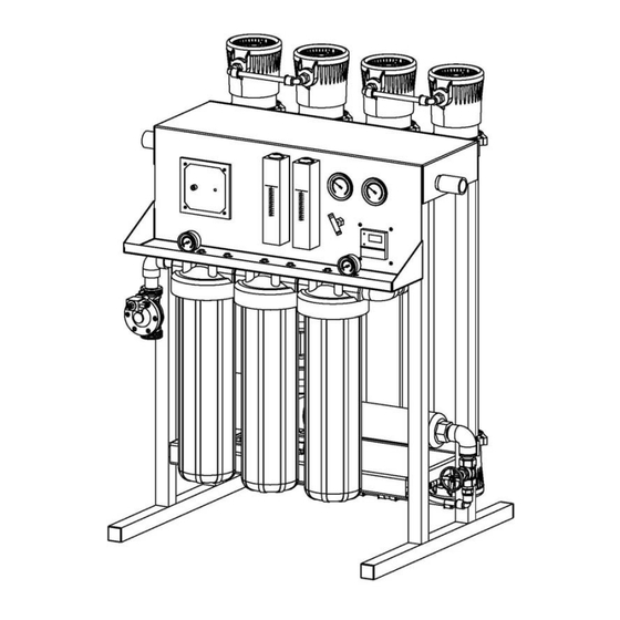
Page 15: Ct-4000, Ct-5000, Ct-7000 System Identification
CT-4000, CT-5000, CT-7000 SYSTEM IDENTIFICATION FIGURE 1A ENGF-107 REV. A 01/11 © 2011 AXEON Water Technologies... - Page 16 17. Pressure Switch – Turns the Pump off at 15 PSI feed pressure 18. Permeate check Valve- Protects membranes from back pressure 19. Pressure Vessels – Houses Membrane Elements 20. TDS Meter – Reads the quality of the permeate water ENGF-107 REV. A 01/11 © 2011 AXEON Water Technologies...
- Page 17 FIGURE 1B FIGURE 1C ENGF-107 REV. A 01/11 © 2011 AXEON Water Technologies...
- Page 18 FIGURE 1D FIGURE 1E ENGF-107 REV. A 01/11 © 2011 AXEON Water Technologies...
- Page 19 FIGURE 1F Note: A portion of the frame has been removed to expose components. ENGF-107 REV. A 01/11 © 2011 AXEON Water Technologies...
-
Page 20: Ct-4000 Membrane Flow Diagram
CT-4000 MEMBRANE FLOW DIAGRAM FIGURE 1G Note: Black arrows represent concentrate water and white arrows represent permeate water. ENGF-107 REV. A 01/11 © 2011 AXEON Water Technologies... -
Page 21: Ct-5000 Membrane Flow Diagram
CT-5000 MEMBRANE FLOW DIAGRAM FIGURE 1H Note: Black arrows represent concentrate water and white arrows represent permeate water. ENGF-107 REV. A 01/11 © 2011 AXEON Water Technologies... -
Page 22: Ct-7000 Membrane Flow Diagram
CT-7000 MEMBRANE FLOW DIAGRAM FIGURE 1I Note: Black arrows represent concentrate water and white arrows represent permeate water. ENGF-107 REV. A 01/11 © 2011 AXEON Water Technologies... -
Page 23: System Purging
#15. (Figure 1B, Page 16) 6. Fully open the throttle valve #13 (Counter Clockwise). (Figure 1B, Page 16) Lever Inline Lever Offset Operating Position Bypass Position FIGURE 2 ENGF-107 REV. A 01/11 © 2011 AXEON Water Technologies... -
Page 24: Initial Start-Up
Adjust the pump throttle valve and concentrate valve until the correct flow is achieved. For example, CT-4000 should be adjusted until it produces about 4000 GPD or 2.77 GPM of permeate (product water) at 77˚F. Design flow might be achieved below 150 PSI. -
Page 25: Design Basis For Ct-4000, Ct-5000, Ct-7000
DESIGN BASIS FOR CT-4000, CT-5000, CT-7000 WARNING: NEVER EXCEED THE MAXIMUM PRESSURE RATING OF YOUR SYSTEM. ENGF-107 REV. A 01/11 © 2011 AXEON Water Technologies... -
Page 26: Operating Do's & Don'ts
NOTE: PRECIPITATION CAN SCALE OR FOUL MEMBRANES AND MUST BE PREVENTED. Check your feed water chemistry and pre-treat the water and/or reduce the system’s recovery as required. If necessary, consult with your local dealer or distributor. ENGF-107 REV. A 01/11 © 2011 AXEON Water Technologies... - Page 27 2.77 gpm at 100 psi; however the same system installed in Maine – much colder feed water – may require 150 psi to produce the same amount of permeate. Never exceed 150 psi. ENGF-107 REV. A 01/11 © 2011 AXEON Water Technologies...
- Page 28 % Rejection = (Feed TDS – Product TDS)/ (Feed TDS) x 100 ADJUSTING THE THROTTLE VALVE To decrease the pressure turn the handle clockwise. To increase the pressure turn the handle counter clockwise. (Figure 3, Page 23) FIGURE 3 ENGF-107 REV. A 01/11 © 2011 AXEON Water Technologies...
-
Page 29: Membrane Removal & Replacement
EACH MEMBRANE ELEMENT HOUSING, SO MARK EACH HOUSING PRIOR TO REMOVING THE MEMBRANE ELEMENTS. THE BRINE SEAL IS A RUBBER SEAL THAT PROTRUDES ON ONE SIDE OF THE MEMBRANE AND IS ALWAYS ON THE FEED SIDE OF THE MEMBRANE ELEMENT. ENGF-107 REV. A 01/11 © 2011 AXEON Water Technologies... - Page 30 SOLUTION. THE MEMBRANES MUST BE FLUSHED FOR AT LEAST 1 HOUR TO REMOVE THE PRESERVATIVE FROM THE MEMBRANE. DISCARD ALL OF THE PERMEATE AND CONCENTRATE, WHICH IS PRODUCED DURING THE FLUSH PERIOD. ENGF-107 REV. A 01/11 © 2011 AXEON Water Technologies...
- Page 31 FIGURE 4 View from the back of CT-4000, CT-5000, and CT-7000 reverse osmosis system. ENGF-107 REV. A 01/11 © 2011 AXEON Water Technologies...
-
Page 32: Flushing The System
4. Repeat this process at least once a month. During the shutdown period, the plant must be kept frost-free, or the temperature must not exceed 113° F (45° C). Preparing unit for shipment: ENGF-107 REV. A 01/11 © 2011 AXEON Water Technologies... - Page 33 9. Drain the flow meters. 10. Allow the system to drain for a minimum of eight hours or until the opened ports quit dripping. 11. After draining is complete, reconnect all of the plumbing. ENGF-107 REV. A 01/11 © 2011 AXEON Water Technologies...
-
Page 34: Reverse Osmosis Troubleshooting
Clean with high pH Organic Fouling cleaner. Check Chlorine feed equipment and Chlorine Oxidation de-chlorination system. Improve pretreatment. Check all Abrasion of membrane by Crystalline filters for media leakage. Material ENGF-107 REV. A 01/11 © 2011 AXEON Water Technologies... - Page 35 77° F. Check your permeate flow meter to determine the permeate flow rate. NOTE: TO DETERMINE THE TEMPERATURE CORRECTION FACTOR, LOCATE THE TEMPERATURE CORRECTION TABLE IN THIS USER’S MANUAL AND FOLLOW THE DIRECTIONS ENGF-107 REV. A 01/11 © 2011 AXEON Water Technologies...
-
Page 36: Temperature Correction Factors For Membrane
Find the temperature correction factor (TCF) from the table below. Divide the rated permeate flow at 77° F by the temperature correction factor. The result is the permeate flow at the desired temperature. (See example on the next page) ENGF-107 REV. A 01/11 © 2011 AXEON Water Technologies... - Page 37 Contact your local dealer or distributor. Prior to making the call, have the following information available: system installation date, serial number, daily log sheets, current operating parameters (e.g. flow, operating pressures, pH, etc.), and a detailed description of the problem. ENGF-107 REV. A 01/11 © 2011 AXEON Water Technologies...
-
Page 38: Operation
Concentrate Flow (gpm) Recovery % Feed Temperature Feed TDS (ppm) Permeate TDS (ppm) Rejection % Feed PH Permeate PH Scale Inhibitor Feed (ppm) Iron (mg/L) Free Chlorine (mg/L) Hardness (gpg CaCO3) ENGF-107 REV. A 01/11 © 2011 AXEON Water Technologies... -
Page 39: Drawings
DRAWINGS FIGURE 5 ENGF-107 REV. A 01/11 © 2011 AXEON Water Technologies... - Page 40 FIGURE 6 ENGF-107 REV. A 01/11 © 2011 AXEON Water Technologies...
- Page 41 FIGURE 7 ENGF-107 REV. A 01/11 © 2011 AXEON Water Technologies...
- Page 42 FIGURE 8 ENGF-107 REV. A 01/11 © 2011 AXEON Water Technologies...
- Page 43 Note: A portion of the frame has been removed to expose components. FIGURE 9 ENGF-107 REV. A 01/11 © 2011 AXEON Water Technologies...
- Page 44 CT-4000 SYSTEM PART LIST Item No. Qty. Part No. Description 1……………2………..200901……GAUGE, BTM, NO FILL, 0-100PSI/BAR, 2” DIA 2……………1………..204914……VALVE, SOLENOID, N/C, UL, 220V, 1” FNPT 3……………1………..200640……CART, SEDIMENT, POLYPRO, 4.5”x 20”, 5 MIC 4……………1………..200663……CARTRIDGE, CARBON, BLOCK, 4.5”x 20”, 10 MIC 5……………1………..200639……CART, SEDIMENT, POLYPRO, 4.5”x 20”, 1 MIC 6……………3………..203649……HOUSING, FILTER, BLK/BLU, 4.5”x 20”, 1”...
- Page 45 16………….1………..200967……VALVE, CHECK, PVC, 1”x 1” FNPT 17………….1………..200857……CONT, COMPUTER, MINITROL, 110/220V, 1PH 18………….6………..200598……SNAP RING, DELRIN, 4” 19………….3………..200597……END PLUG, CLOSED, GTX, 4”, 1/2” FNPT 19………….3………..200596……END PLUG, OPEN, GTX, 4”, 1/2" FNPT 20………….6……….200588……CLAMP, SADDLE, NYLON, BLK, 4”, PVC/FRP ENGF-107 REV. A 01/11 © 2011 AXEON Water Technologies...
- Page 46 16………….1………..200967……VALVE, CHECK, PVC, 1”x 1” FNPT 17………….1………..200857……CONT, COMPUTER, MINITROL, 110/220V, 1PH 18………….8………..200598……SNAP RING, DELRIN, 4” 19………….4………..200597……END PLUG, CLOSED, GTX, 4”, 1/2” FNPT 19………….4………..200596……END PLUG, OPEN, GTX, 4”, 1/2" FNPT 20………….6……….200588……CLAMP, SADDLE, NYLON, BLK, 4”, PVC/FRP ENGF-107 REV. A 01/11 © 2011 AXEON Water Technologies...
- Page 47 CT-4000 FLOW DIAGRAM ENGF-107 REV. A 01/11 © 2011 AXEON Water Technologies...
- Page 48 CT-5000 FLOW DIAGRAM ENGF-107 REV. A 01/11 © 2011 AXEON Water Technologies...
- Page 49 CT-7000 FLOW DIAGRAM ENGF-107 REV. A 01/11 © 2011 AXEON Water Technologies...
- Page 50 110/220V 50/60 Hz 1 PHASE ELECTRICAL SCHEMATIC Minitrol ENGF-107 REV. A 01/11 © 2011 AXEON Water Technologies...
- Page 51 208/220V 50/60 Hz 3 PHASE ELECTRICAL SCHEMATIC Minitrol ENGF-107 REV. A 01/11 © 2011 AXEON Water Technologies...
- Page 52 110/220V 50/60 Hz 1 PHASE ELECTRICAL SCHEMATIC Minitrol IF ENGF-107 REV. A 01/11 © 2011 AXEON Water Technologies...
- Page 53 208/220V 50/60 Hz 3 PHASE ELECTRICAL SCHEMATIC Minitrol IF ENGF-107 REV. A 01/11 © 2011 AXEON Water Technologies...
- Page 54 ENGF-107 REV. A 01/11 © 2011 AXEON Water Technologies...
Need help?
Do you have a question about the CT-4000 and is the answer not in the manual?
Questions and answers