
Related Manuals for Cub Cadet CLT-538


Summary of Contents for Cub Cadet CLT-538
- Page 1 Operator’s Manual Lawn Tractor Model: CLT-538 IMPORTANT: READ SAFETY RULES AND INSTRUCTIONS CAREFULLY. 60 Ottawa Street South, KITCHENER, ONTARIO CANADA N2G 3S7 772C0811 PRINTED IN U.S.A. (11/19/2005)
-
Page 2: Finding Model Number
Copy the model number here: XXX-XXXXXX XXXXXXXXXXX Copy the serial number here: CUB CADET CANADA KITCHENER, ON N2G 4J1 ENGINE INFORMATION The engine manufacturer is responsible for all engine-related issues with regards to performance, power-rating, specifications, warranty and service. Please refer to the engine manufacturer’s Owner’s/Operator’s Manual packed separately with your unit for more information. -
Page 3: Section 1: Important Safe Operation Practices
SECTION 1: IMPORTANT SAFE OPERATION PRACTICES WARNING: This symbol points out important safety instructions which, if not followed, could endanger the personal safety and/or property of yourself and others. Read and follow all instructions in this manual before attempting to operate this machine. Failure to comply with these instructions may result in personal injury. -
Page 4: Slope Operation
23. Muffler and engine become hot and can cause a 4. Follow the manufacturer’s recommendations for burn. Do not touch. wheel weights or counterweights to improve 24. Check overhead clearances carefully before driving stability. under low hanging tree branches, wires, door 5. -
Page 5: Safe Handling Of Gasoline
e. Use extreme care when approaching blind lock-open device. corners, doorways, shrubs, trees or other e. Extinguish all cigarettes, cigars, pipes and objects that may block your vision of a child other sources of ignition. who may run into the machine. Never fuel machine indoors. - Page 6 8. Never tamper with the safety interlock system or For safety protection, frequently check components other safety devices. Check their proper operation and replace immediately with original equipment regularly. manufacturer’s (O.E.M.) parts only, listed in this 9. After striking a foreign object, stop the engine, manual.
-
Page 7: Section 2: Slope Gauge
SECTION 2: SLOPE GAUGE Use this page as a guide to determine slopes where you may not operate safely. Do not operate your equipment on such slopes. -
Page 8: Section 3: Tractor Set-Up
SECTION 3: TRACTOR SET-UP This unit is shipped WITHOUT GASOLINE. Check oil before starting engine. Do not overfill. After IMPORTANT: assembly, service engine with gasoline and oil as instructed in the separate engine manual packed with your unit. NOTE: 3. Select desired position for the seat, and secure with This owner’s manual covers various models of the two hex screws/knobs removed. -
Page 9: Shipping Brace Removal
Tire Pressure Service the engine with gasoline and oil as instructed in the separate engine manual packed with your tractor. Read instructions carefully. WARNING: Maximum tire pressure under any circumstances is 30 psi. Equal tire Your tractor is shipped with motor oil in the IMPORTANT: pressure should be maintained at all times. -
Page 10: Section 4: Know Your Lawn Tractor
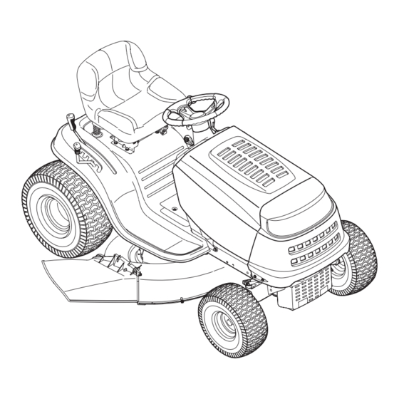
SECTION 4: KNOW YOUR LAWN TRACTOR Figure 5 Speed Control Lever / Parking Brake Ignition Switch Module Clutch-brake Pedal Deck Lift Lever Shift Lever G PTO (Blade Engage) Lever Throttle Control Lever Ammeter (Optional) NOTE: Any reference in this manual to the RIGHT or LEFT side of the tractor is observed from operator’s position. -
Page 11: Throttle Control
Throttle Control NOTE: The pedal must be depressed to start the engine. Refer to Safety Interlock Switches on page 13. CHOKE The throttle control lever is located on the right side of FAST Parking Brake the tractor’s dash panel. This lever controls the speed of To set the parking brake, fully depress the clutch-brake the engine and, and on... -
Page 12: Deck Lift Lever
Deck Lift Lever Ignition Switch Module Found on your tractor’s right fender, WARNING: Never leave a running machine the deck lift lever is used to change unattended. Always disengage PTO, move the height of the cutting deck. To use, shift lever into neutral position, set parking move the lever to the left, then place brake, stop engine and remove key to prevent in the notch best suited for your... -
Page 13: Section 5: Operating Your Lawn Tractor
SECTION 5: OPERATING YOUR LAWN TRACTOR Safety Interlock Switches 3. Depress the REVERSE PUSH BUTTON (Orange, Triangular Button) at the top, right corner of the key This tractor is equipped with a safety interlock system switch module. The red indicator light at the top, left for the protection of the operator. -
Page 14: Setting The Cutting Height
Stopping the Engine NOTE: The parking brake must be set if the operator leaves the seat with the engine running or the engine WARNING: will automatically shut off. If you strike a foreign object, stop the engine, disconnect the spark plug Setting the Cutting Height wire(s) and ground against the engine. -
Page 15: Driving On Slopes
Using the Deck Lift Lever NOTE: When operating the unit initially, there will be little difference between the highest two speeds until To raise the cutting deck, move the deck lift lever to the after the belts have seated themselves into the pulleys left, then place it in the notch best suited for your during the break-in period. -
Page 16: Section 6: Making Adjustments
• Do NOT attempt to mow heavy brush and weeds • Always position the throttle control lever in the and extremely tall grass. Your tractor is designed to FAST (rabbit) position and allow it to remain there mow lawns, NOT clear brush. while mowing. -
Page 17: Seat Adjustment
Side to Side disc can be found on the right side of the transmission in the rear of the tractor. Adjust if necessary as follows: If the cutting deck appears to be mowing unevenly, a side to side adjustment can be performed. Adjust if •... -
Page 18: Section 7: Maintaining Your Lawn Tractor
SECTION 7: MAINTAINING YOUR LAWN TRACTOR WARNING: • Remove drain plug and drain oil into a suitable Before performing container with a capacity of no less than 64 oz. maintenance or repairs, disengage PTO, • Service the oil filter (if so equipped) as instructed move shift lever into neutral position, set in the separate engine manual packed with your parking brake, stop engine and remove key to... -
Page 19: Cleaning The Engine And Deck
Front Axles NOTE: Refer to page 23 for information regarding this other separately-available attachments & Each end of the tractor’s front pivot bar may be accessories for your tractor. equipped with a grease fitting. Lubricate with a grease gun after every 25 hours of tractor operation. Cleaning the Engine and Deck Any fuel or oil spilled on the machine should be wiped off promptly. -
Page 20: Section 8: Service
SECTION 8: SERVICE Cutting Deck Removal To remove the cutting deck, proceed as follows: Idler Bracket • Place the PTO (Blade Engage) lever in the disengaged (OFF) position. • Engage the parking brake. • Lower the deck by moving the deck lift lever into the bottom notch on the right fender. -
Page 21: Cutting Blades
could change the polarity and result in damage to your that the fuse has not blown. It can be found under the engine’s alternating system. hood mounted behind the dash panel on the right side. WARNING: Always use a fuse with the Charging same amperage capacity for replacement. -
Page 22: Changing The Transmission Drive Belts
WARNING: Avoid the possibility of a pinching injury. Do not place your fingers on Blade Separation the idler spring or between the belt and a pulley while removing the belt. All belts on your tractor are subject to wear and should be replaced if any signs of wear are present. -
Page 23: Section 9: Off-Season Storage
Idler Bracket Idler Bracket Engine Pulley Engine Pulley Deck Idler Pulleys Deck Idler Pulleys Figure 20 (38”) Figure 21 (42”) SECTION 9: OFF-SEASON STORAGE Clean and lubricate the tractor as instructed in Section 7: Follow the instructions in the Service, Storage & MAINTAINING YOUR LAWN TRACTOR on page 18 of this Specifications section of the separate engine manual manual before storing for an extended period. -
Page 24: Section 11: Troubleshooting
SECTION 11: TROUBLESHOOTING Trouble Possible Cause(s) Corrective Action Engine fails to start PTO engaged. Place PTO lever in disengaged (OFF) position. Parking brake not engaged. Engage parking brake. Spark plug wire(s) disconnected. Connect wire(s) to spark plug(s). Throttle control lever not in correct Place throttle control in CHOKE position. -
Page 25: Section 12: Three Year Limited Warranty
SECTION 12: THREE YEAR LIMITED WARRANTY For three (3) years from the date of original purchase of our products, we will either repair or replace, at its option, free of charge, F.O.B. Factory or authorized service firm, any part found to be DEFECTIVE IN MATERIAL and WORKMANSHIP for the original purchaser. - Page 26 �� ��� �� ������ ��������� ���� ����� �� ��� ���� �������� �� ��� �� ����� ����� ���������� � ������� ������� ����� ����� ���������� ������ � � � � � �� � �� � �� � �� �� �� �� �� ��...
-
Page 27: Parts List
Parts List PART Pièces N° DE N° DE RÉF PIÈCE DESCRIPTION DESCRIPTION 710-0599 Hex Wash S-Tapp Scr 1/4-20 x .50 Vis autotaraudeuse à rondelle hex. détachées 1/4-20 x 0,50 710-0604A Hex Wash HD TT Scr 5/16-12 x .625 Vis taraudée 5/16-12 x 0,625 710-0751 Hex Bolt 1/4-20 x .62 Gr. - Page 28 �� � � �� �� �� �� �� � �� � � � � �� �� �� �� �� �� � � �� �� �� �� �� �� �� �� � �� �� �� �� �� �� �� �� � ��...
- Page 29 Parts List PART Pièces N° DE N° DE RÉF PIÈCE DESCRIPTION DESCRIPTION 710-1268 Hex B-Tapp Wash Scr #10-16 x .38 Vis taraudeuse N° 10-16 x 0,38 détachées 712-04063 Flange Locknut 5/16-18 Gr. F, Nylon Contre-écrou à embase 5/16-18 Qual. F, nylon 712-3027 Hex L-Flanged Nut 1/4-20 Contre-écrou à...
- Page 30 �� � �� �� �� � �� �� �� �� �� �� �� � �� � � �� � �� �� �� �� �� � � �� �� �� � �� �� �� �� �� �� �� �� �� �� �...
- Page 31 Parts List PART Pièces N° DE N° DE RÉF PIÈCE DESCRIPTION DESCRIPTION 617-04024 Steering Gear Assembly Boîtier de direction détachées 710-0376 Hex Scr 5/16 x 1,00 Gr. 5 Vis à tête hex. 5/16 x 1,00 Qual. 5 710-0643 Hex Screw 5/16-18 x 1.00 Special Vis à...
- Page 32 �� �� � �� �� �� � �� �� �� �� �� �� �� �� �� � �� �� �� �� � �� �� �� �� � �� � ������ �������� � �� � �� �� � �� � �� ��...
- Page 33 Parts List PART Pièces N° DE N° DE RÉF PIÈCE DESCRIPTION DESCRIPTION 618-04034 Transmission Ass’y Transessieu détachées 647-04035 Shift Lever Ass’y Ensemble de levier de changement 710-0176 Hex Scr 5/16-18 x 2.75 Vis à tête hexagonale 5/16 x 2,75 710-0227 Hex Wash HD AB S-Tapp Scr #8-.50 Vis taraudée N°.
- Page 34 �� �� �� �� �� �� �� �� �� �� �� �� �� �� � � �� �� �� � �� �� � �� �� � �� � �� � �� �� � �� � �� �� �� �� �� ��...
- Page 35 Parts List PART Pièces N° DE N° DE RÉF PIÈCE DESCRIPTION DESCRIPTION détachées 17962 Switch Plate Plaque de contacteur 647-04040 PTO Handle Manette de la prise de force 710-0224 Hex AB-Tap Scr #10 x .50" Lg. Vis hexagonale taraudée N° 10 x 0,50 po de lg 710-0599 Hex Wash S-Tapp Scr 1/4-20 x .50 Vis autotaraudeuse à...
- Page 36 � � � � � � � � � � �� �� �� �� �� �� �� �� � �� �� �� �� �� � �� �� �� �� �� �� �� ��...
- Page 37 Parts List PART Pièces N° DE N° DE RÉF PIÈCE DESCRIPTION DESCRIPTION détachées 732-0614 Wire Ring Fil de nuque 716-0231 “E” Ring Bague en «E» 736-0336 Flat Washer 5/8 ID x 1.0 OD x .030 Rondelle plate 5/8 DI x 1,0 DE x 0,030 736-0337 Flat Washer 5/8 ID x 1.0 OD x 0.040 Rondelle plate 5/8 DI x 1,0 DE x 0,040...
- Page 38 38” Deck/Plateau de coupe de 38 po � � �� �� � � �� �� �� �� �� �� � �� � �� �� �� �� �� �� �� �� �� �� �� � �� �� �� � �� � ��...
- Page 39 Parts List PART Pièces N° DE N° DE RÉF PIÈCE DESCRIPTION DESCRIPTION détachées 618-04197 Pulley Spindle Ass’y 5.75 dia. Fusée diamètre de 5,75 683-04428 Deck Hanger Brkt. Ass'y Support du plateau de coupee 683-04138 Deck Brake Assembly Frein du plateau de coupe 683-04161 Deck Shell, 38"...
- Page 40 �� � � �������� ������ �������� �� �� ������� ������ ��� �� �� � � �������� � �� �������� ������ ��� �� �� � � �� �� �� �� �� �� �� � � �������� ������ �������� � ������� ������ ��� �...
- Page 41 Parts List PART Pièces N° DE N° DE RÉF PIÈCE DESCRIPTION DESCRIPTION détachées 710-0227 Hex Wash HD AB S-Tapp Scr #8-.50 Vis taraudée N°. 8-0,50 710-0599 Hex Wash S-Tapp Scr 1/4-20 x .50 Vis autotaraudeuse à rondelle hex. 1/4-20 x 0,50 710-0726 Hex Wash HD Scr 5/16-12 x .75 Vis taraudee 5/16-12 x 0,75...
- Page 42 NOTES: For parts and/or accessories refer to customer support on page 2. Adressez-vous au «Service après-vente» à la page 2 pour ce qui concerne les pièces et/ou accessoires.
Need help?
Do you have a question about the CLT-538 and is the answer not in the manual?
Questions and answers