
Related Manuals for Hubbell Electric Heater Company HE


Summary of Contents for Hubbell Electric Heater Company HE
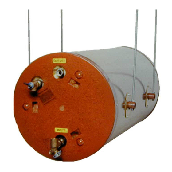
- Page 1 OPERATING AND MAINTENANCE MANUAL FOR COMMERCIAL HORIZONTAL CEILING-HUNG ELECTRIC WATER HEATER ELECTRIC HEATER COMPANY BASE MODELS “ HE and HSE ”...
-
Page 2: Warning / Caution
A qualified installer is a person who has licensed training and a working knowledge of the applicable codes regulation, tools, equipment, and methods necessary for safe installation of an electric resistance water heater. If questions regarding installation arise, check your local plumbing and electrical inspectors for proper procedures and codes. -
Page 3: Table Of Contents
SECTION TITLE GENERAL DESCRIPTION AND CONSTRUCTION INSTALLATION SCHEDULED MAINTENANCE AND OPERATION TROUBLESHOOTING SERVICING AND REPLACEMENT OF PARTS MISCELLANEOUS CHARTS AND FORMULAS TABLE OF CONTENTS PAGE #... -
Page 5: Tank Connections
GENERAL DESCRIPTION AND CONSTRUCTION GENERAL DESCRIPTION This book describes a packaged electric water heater that is a stationary, self-contained unit. The complete assembly consists of the storage tank, immersion electric heating element(s), thermostat, safety relief valve, safety high temperature cut out, and any other required electrical operating control. -
Page 6: Heating Element
Manual Reset HEATING ELEMENT The water heater is supplied with an electric immersion heating element assembly(s), composed of incoloy or copper sheathed elements that are brazed into a brass flange. Each assembly is fastened to a corresponding tank flange using a gasket and four (4) 3/8-16 x 1-inch long hex head steel bolts and nuts. - Page 7 DRIP PAN (Optional) A drip pan assembly may be supplied as an option with the unit. It is designed to mount directly beneath the water heater as shown in the sketch on page 4. SWAY RESISTANT MOUNTS (Optional) Optional sway resistant mounts may be supplied to further secure the tank from longitudinal movement.
-
Page 8: Water Heater Placement
3. Install 3/8” diameter threaded rod (not supplied) into the four (4) mounting assemblies on the tank. 4. Install drip pan, if supplied. 5. The water heater should be protected from freezing and waterlines insulated to reduce energy and water waste. 6. Leave a minimum of 13” clearance for element withdrawal, if necessary. -
Page 9: Piping Installation
PIPING INSTALLATION NOTE: The most effective means for preventing deterioration from accelerated corrosion due to galvanic and stray current is the installation of dielectric fittings/unions. The installation of these fittings is the responsibility of the installing contractor. 1. Thread cold water inlet and diffuser assembly into tank. Diffuser slots must be pointing down toward the bottom of the tank. -
Page 10: Electrical Installation
FILLING THE HEATER 1. Completely close the drain valve. 2. Open the highest hot water faucet to allow all air to escape from piping. 3. Open the valve to the cold water inlet and allow the heater and piping system to completely fill, as indicated by a steady flow of water from the open faucet. -
Page 11: Quarterly Inspection
MAINTENANCE AND OPERATION The water heater is automatic in its operation. It will maintain a full tank of water at the temperature setting of the thermostat. The water heater should not be turned on without first making sure that the tank is full of water and that all air has been released. -
Page 12: Annual Inspection
4. Inspect ceiling supports for tightness and/or damage. 5. Check for loose electrical connections. Tighten as necessary. ANNUAL INSPECTION 1. Flush tank as follows a. Shut off power supply. b. Close valve on hot water outlet piping. c. Open valve on drain piping. d. -
Page 13: Troubleshooting
SECTION IV – Symptom No hot water Circuit breaker tripped at source. Reset circuit breaker. High limit switch tripped. Loose wires. Heating element inoperable. Low line voltage. Faulty thermostat. Magnetic contactor does not energize. Water temperature Faulty thermostat. below settings at all times Heating element not working on all phases... -
Page 14: Vservicing And Replacement Of Parts
SECTION V - Before servicing or replacing any part make sure to turn the power supply switch to the OFF position. SURFACE TEMPERATURE HIGH LIMIT CUT-OFF 1. Disconnect power from unit. 2. Remove access cover. 3. Disconnect the four (4) 14 gauge wires. Control Wires 4. -
Page 15: Heating Element
HEATING ELEMENT 1. Disconnect power from unit. 2. Shut off incoming water supply. 3. Attach hose to drain connection. 4. Lift manual release lever on relief valve to let air into system or break union on outgoing water line. 5. Drain water from tank. 6. -
Page 17: Immersion Thermostat
IMMERSION THERMOSTAT 1. Disconnect power from unit. 2. Remove access cover and locate thermostat. 3. Remove high limit cover screw and cover. 4. Disconnect the two (2) 14 gauge wires. 5. Remove capillary tube and bulb from thermowell. 6. Remove two (2) mounting screws. 7. -
Page 18: Magnetic Contactor
MAGNETIC CONTACTOR 1. Disconnect power from unit. 2. Disconnect line and load wires to contactor. 3. Disconnect two (2) 14 gauge control circuit wires. 4. Loosen two (2) holding screws and remove contactor. 5. Replace with new contactor using reverse procedure. -
Page 19: Relief Valve
RELIEF VALVE 1. Disconnect power from unit. 2. Shut off incoming water supply. 3. Lift test lever on relief valve to relieve pressure in tank. 4. Disconnect overflow piping. 5. Unscrew relief valve, remove assembly and replace with new one. 6. -
Page 20: Miscellaneous Charts And Formulas
SECTION VI – FORMULAS 3-PHASE ELEMENT CHART Power (kW) Element Part # 208V 240V 480V 2-38683N 3-38683N 4-38683N 5-38683N 6-38683N 7-38683N 8-38683N 9-38683N 10-38683N ---- 11-38683N 17.3 ---- ---- MISCELLANEOUS CHARTS AND FORMULAS Immersion Length Hairpin 13" 57.6 13" 43.2 13"... - Page 21 SINGLE PHASE ELEMENT CHART Element Part # 120V 208V CH-FO-358 ---- CH-FO-408 ---- CH-FO-508 ---- CH-FO-608 2000 CH-FO-304 ---- CH-FO-354 ---- CH-FO-404 ---- CH-FO-454 ---- CH-FO-504 ---- CH-FO-604 1500 TGB-1203-480 ---- TGB-1353-480 ---- TGB-2257L 2500 TGB-1207-240 TGB-1303-480 ---- TGB-1403-480 ---- TGB-2257-240 ---- TGB-2257-480...
-
Page 22: Torque Values
TORQUE VALUES 18-8 S/S BOLT SIZE IN.-LBS. IN.-LBS. 4-40 4-48 5-40 5-44 6-32 6-40 12.1 8-32 19.8 8-36 22.0 10-24 22.8 10-32 31.7 1/4-20 75.2 1/4-28 94.0 5/16-18 5/16-24 3/8-16 3/8-24 7/16-14 7/16-20 1/2-13 1/2-20 9/16-12 9/16-18 5/8-11 1110 5/8-18 1244 3/4-10 1530...
Need help?
Do you have a question about the HE and is the answer not in the manual?
Questions and answers