
Related Manuals for Hubbell Electric Heater Company J25


Summary of Contents for Hubbell Electric Heater Company J25
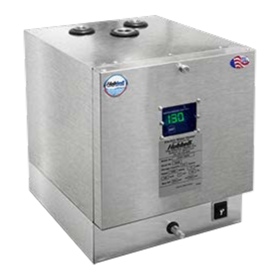
- Page 1 INSTALLATION, OPERATION AND MAINTENANCE MANUAL FOR COMPACT POINT-OF-USE ELECTRIC WATER HEATER BASE MODEL “J25” 2018 Edition...
- Page 2 HUBBELL ELECTRIC HEATER COMPANY P.O. BOX 288 STRATFORD, CT 06615 PHONE: (203) 378-2659 FAX: (203) 378-3593 INTERNET: http://www.hubbellheaters.com -- IMPORTANT -- Always reference the full model number and serial number when calling the factory. The following information should be noted at time of installation and retained for future reference.
- Page 3 WARNING / CAUTION 1. Please read all instructions prior to installing water heater. 2. Tank is to be completely filled with water and all air is to be vented before energizing. 3. Due to the rigors of transportation, all connections should be checked for tightness before heater is placed in operation.
-
Page 4: Table Of Contents
Table of Contents SECTION I - GENERAL INFORMATION ....................5 GENERAL DESCRIPTION ......................... 5 CONSTRUCTION ............................6 TANK ............................... 6 TANK CONNECTIONS .......................... 6 HEATING ELEMENT ..........................6 ELETRONIC TEMPERATURE CONTROLLER ................... 6 HIGH TEMPERATURE CUT-OFF SWITCH ..................6 SAFETY RELIEF VALVE ........................6 OUTER SHELL AND INSULATION ..................... -
Page 5: Section I - General Information
SECTION I - GENERAL INFORMATION GENERAL DESCRIPTION This manual describes a packaged electric water heater that is a stationary, self-contained unit. The complete assembly consists of the storage tank, immersion electric heating element, digital controller, hi-limit thermostat with manual reset, safety relief valve, and any other required electrical operating control. -
Page 6: Construction
CONSTRUCTION TANK The 2.5-gallon storage tank is constructed of 304 stainless steel and is designed for a maximum allowable working pressure of 150 psi (300 psi TP). TANK CONNECTIONS The heater is supplied with separate ½” FNPT cold water and hot water connections. A ¾-inch FNPT connection is located on the top of the heater for mounting a combination safety temperature and pressure relief valve. -
Page 7: Cover Legs (Optional)
COVER LEGS Adjustable, stainless steel cover legs, shown in Figure , are available in lieu of wall support rails. ON/OFF POWER SWITCH (OPTIONAL) Rocker switch is available to power the unit down externally, shown in Figure 1. Figure 5: Cover Legs ELECTRIC CORD (OPTIONAL) For 120V models 1440W or less, an electric cord can be installed and plugged into a standard 15A wall socket. -
Page 8: Filling The Heater
1. Connect the cold water inlet and hot water outlet to the appropriate connections; refer to Figure 8. 2. Provide a shut off valve in the cold water line. Mark for future emergency use. 3. If pressure reducers or any other restrictions are put in the cold water line, special precautions should be taken. -
Page 9: Final Checks
FINAL CHECKS 1. Check all connections for tightness. 2. Complete following checklist to ensure that all the above steps are completed: Unit unpacked and checked for damage. Heater properly located. Heater properly secured to wall (If option was chosen). Cold water line connected to cold water inlet on tank. Shut-off valve installed in cold water line. - Page 10 Dielectric Inlet Valve Union Piping to Hot Water Temperature & Pressure Dielectric Relief Valve Union Relief Valve Discharge Pipe Piping from Cold Water Drain Figure 8: Recommended Installation Diagram **NOTE: ONLY TEMPERATURE AND PRESSURE RELIEF VALVE SUPPLIED BY MANUFACTURER**...
-
Page 11: Section Iii - Controller Operation
SECTION III – CONTROLLER OPERATION ABOUT THE CONTROLLER The Hubbell Electronic Temperature Controller provides the user with the ability to control and customize the operation of their water heater. The 4-digit display shows the status of the water heater, and can display useful information such as current temperature conditions inside the tank, error notifications, and more. -
Page 12: Child Lock
To activate vacation override, press the button on the controller. The display will show “A-07”, indicating the default vacation length of 7 days. The minimum vacation length is 2 days and the maximum is 99 days. Use the buttons to adjust the desired length of time to use vacation mode. -
Page 13: Diagnostics
To access the options menu, from the home screen, press and hold the button until the display reads “diF” (differential), this is the first selection in the options menu. To navigate the options menu, continue to press the button to cycle through the available options until the desired option is displayed. -
Page 14: Differential
DIFFERENTIAL A temperature differential represents how far the water temperature can fall before the water heater must call for heat again. For example, if the setpoint is 120°F and the differential is 10°F, then after satisfying at 120°F, the water temperature must fall to 110°F before the water heater will call for heat. -
Page 15: Troubleshooting
satisfying the utility’s need for peak control while also offering a great deal of flexibility for the end user. Programs for the ETC are determined by the electric utility. Once programmed, the ETC automatically controls the water heater, saving energy without any worry or inconvenience to the user. -
Page 16: Section Iv - Scheduled Maintenance And Operation
SECTION IV - SCHEDULED MAINTENANCE AND OPERATION WARNING / CAUTION Before performing any maintenance procedure, make certain power supply is OFF and cannot accidentally be turned on. Exposure to 125°F or hotter water can cause scalding injuries. Appropriate caution must be taken when using hot water. -
Page 17: Annual Inspection
ANNUAL INSPECTION 1. Flush tank as follows: a. Shut off power to water heater. b. Close the valve on the cold-water line to the heater. c. Remove drain plug and attach a hose to the drain coupling at the base of the water heater, refer to Figure 1 for drain location. -
Page 18: Section V - Troubleshooting
SECTION V – TROUBLESHOOTING Troubleshooting instructions can be found in Table 2 Table 2: Troubleshooting Symptom Probable Cause Corrective Action / Remedy No hot water Circuit breaker tripped at Reset circuit breaker. source High limit switch tripped Reset high limit switch. Loose wires Tighten wires. -
Page 19: Section Vi - Servicing & Replacement Of Parts
SECTION VI - SERVICING & REPLACEMENT OF PARTS WARNING / CAUTION Before servicing or replacing any part, make sure to turn the power supply switch to the OFF position. HIGH TEMPERATURE CUT-OFF SWITCH 1. Disconnect power from unit. 2. Remove access cover. 3. -
Page 20: Heating Element
HEATING ELEMENT 1. Disconnect power from unit. 2. Shut off incoming water supply. 3. Attach hose to drain connection. 4. Lift manual release lever on relief valve to let air into system or break union on outgoing water line. 5. Drain water from tank. 6. -
Page 21: Relief Valve
RELIEF VALVE 1. Disconnect power from unit. 2. Shut off incoming water supply. 3. Lift test lever on relief valve to relieve pressure in tank. 4. Disconnect overflow piping. 5. Unscrew relief valve, remove assembly and replace with new one. 6. -
Page 22: Section Vii - Warranty
SECTION VII – WARRANTY LIMITED WARRANTY AND TANK REPLACEMENT POLICY The Electric Heater Co., (hereinafter called, the "Company"), offers the following warranty to the purchaser/owner of this electric water heater. Carefully read the entire warranty. Once you buy this product, the Company assumes you agree with the conditions and limitations of this warranty, and you accept the purchaser's/owner's responsibility for installation and care of the heater. -
Page 23: How To Obtain Service Assistance
Limited Warranty and Tank Replacement Policy that the manufacturer relies on the diligence of the purchaser/owner in the installation and future use. Diligence on the part of the user is essential to reduce the risk from known hazards associated with water heaters. Installation: The heater must be installed in accordance with established codes and the manufacturer's guidelines. - Page 24 P.O. BOX 288 STRATFORD, CT 06615-0288 PHONE: (203) 378-2659 FAX: (203) 378-3593 INTERNET: http://www.hubbellheaters.com/...
Need help?
Do you have a question about the J25 and is the answer not in the manual?
Questions and answers