Table of Contents
Advertisement
Advertisement
Table of Contents

Related Manuals for Cactus V6


Summary of Contents for Cactus V6
- Page 1 User Manual Wireless Flash Transceiver...
-
Page 2: Table Of Contents
Table of Contents Getting to Know the Cactus V6 Cautions and Warnings Major Specif ications Package Contents Nomenclature LCD Panel Compatibility TTL Pass-through Getting Started 10. Flash Prof ile: Choosing, Learning, and Copying 11. Flash Triggering 12. Remote Manual Power Control... - Page 3 13. Camera Shutter Release 14. Advanced Operations 15. Personalizing the V6 16. Working with Cactus Gear 17. LED Signal Guide 18. USB Connection 19. Optional Accessories 20. Troubleshooting 21. Notices 22. Warranty...
-
Page 4: Getting To Know The Cactus V6
1. Getting to Know the Cactus Thank you for purchasing the Cactus Wireless Flash Transceiver V6. The Cactus V6 is a multifunctional wireless flash transceiver that allows you to command different brands’ flashes off camera with remote power control. You can position your lights at any angle, direction, and distance —... - Page 5 For flash models that have not been included in the prof ile list, the V6 can still work with it by learning its flash prof ile. Check Section 7 .1.3 for details of which flashes are eligible for the flash prof ile learning program.
- Page 6 Whether built-in or obtained from the learning program, the flash prof ile stored in the V6 can virtually command the flash to produce ANY power level within the maximum output, and even exceeds what the flash menu allows you to do: 1.
-
Page 7: Cautions And Warnings
5. Do not operate the device in the presence of flammable gases or fumes. 6. Do not dissemble. 7 . Do not crush and do not expose the V6 to any shock or force such as hammering, dropping, or stepping on it. -
Page 8: Major Specifications
3. Major Specifications • Working radio frequency: 2.4 GHz • Number of channels: 16 • Number of groups: 4 • Support sync speed up to 1/1,000 second (subject to camera’s sync speed limitation) • Maximum effective distance: 100 meters • Operating temperature: -20°C to +50°C •... -
Page 9: Package Contents
4. Package Contents V6 Transceiver Flash Stand FS-2 Album & User Manual... -
Page 10: Nomenclature
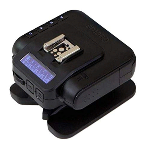
5. Nomenclature MULTI-SYSTEM SHOE (FEMALE) TEST BUTTON/ LCD DISPLAY SHUTTER RELEASE BUTTON LANYARD LOOP OPTICAL SENSOR X-SYNC PORT MINI USB PORT GROUP BUTTONS MODE SWITCH... - Page 11 MULTI-SYSTEM SHOE (MALE) HOT SHOE TRIPOD MOUNT LOCK LEVER SELECTION DIAL BATTERY DOOR OK BUTTON MENU BUTTON LED STATUS INDICATOR...
-
Page 12: Lcd Panel
6. LCD Panel BATTERY GROUP INDICATOR TX mode POWER LEVEL CHANNEL POWER LEVEL INCREMENT SELECTED FLASH PROFILE RX mode POWER LEVEL BATTERY INDICATOR WIRELESS POWER LEVEL INCREMENT SENSITIVITY GROUP SLAVE MODE CHANNEL DELAY TIMER RELAY MODE INDICATOR INDICATOR... -
Page 13: Compatibility
7. Compatibility The Cactus V6 is both a wireless flash trigger and wireless remote control. While it triggers both portable flashes and studio strobe lights, it also supports remote control features with selected flash models. 7.1.1 Cactus RF60 Flash &... - Page 14 * prof iles working with different versions of the model (e.g. , 580EX II and 580EX) 7.1.3 Flash Models with Analogue TTL Mode The Cactus V6 can learn the prof iles of other flash models that come with an analogue TTL mode, i.e.
- Page 15 (see Section 19) . This includes high trigger voltage portable flash models, and all strobe models with a trigger voltage of 300V or under. The Cactus V6 does not provide remote power control of these flashes and strobes.
- Page 16 To use the V6 as a wireless shutter release, specif ic shutter cables are required. For the list of optional accessories, see Section 19. 7.3.1 Cactus V5 and LV5 Flash The Cactus V6 is compatible with the Triggers Wireless Flash Transceiver V5 and Laser Trigger LV5.
-
Page 17: Ttl Pass-Through
8. TTL Pass-through The V6 transceiver comes with a multi-system shoe that supports TTL pass-through. While the V6 does not transmit TTL signal wirelessly, it is designed to pass TTL signal from camera to flash via the transmitter (TX) and vice versa. - Page 18 AF assist light, second curtain sync, high speed sync/FP shutter) provided by the TTL flash system. To enable TTL pass-through in the V6 TX, press and hold for 2 seconds. The LCD will show the TTL pass-through indicator at the left bottom corner where the channel indicator used to be.
-
Page 19: Getting Started
Camera UNLOCK LOCK To mount the V6 on a camera’s hot shoe mount: 1. Turn the lock lever of the V6 to the left to unlock the multi-system shoe (male) . 2. Slide the V6 into the camera’s hot shoe. - Page 20 3. Turn the lock lever of the V6 to the right to lock the multi-system shoe (male) . 4. When detaching the V6 from the camera’s hot shoe, turn the lock lever to the left to unlock the multi-system shoe (male) .
- Page 21 In TX mode, press and hold while simultaneously turning the selection dial to change the power level of the master flash on the V6 TX (see Section 12.1.1) . – In TX mode with absolute power mode, press any group button together with simultaneously to conf igure the EV offset of the group (see Section 12.2) .
- Page 22 The selection dial is a two-way dial that scrolls easily through different options by turning left or right. Use the dial to: 1. Access menu items and menu options in the conf iguration menu. 2. Adjust the power levels in the TX main screen.
- Page 23 The Cactus V6 transceivers communicate with each other via radio frequency. There are 16 Setting channels available. Always make sure that all of your V6 transceivers are set to the Channel same channel: 1. To set both TX and RX to the same channel, press .
- Page 24 Setting Selecting the Group The group function in the V6 can assign RXs into Group A, B, C, or D, and allows you to choose which group(s) to f ire from the TX unit. 1. All V6 transceivers must be set to the same channel.
- Page 25 5. Pressing the group button(s) of activated groups again on the V6 TX will turn off the group(s) . The V6 RX units that have been set to the off group(s) will not f ire. The V6 will memorize the group selection in both TX and RX when it is switched off.
- Page 26 Applicable modes Menu item Option CHANNEL 1-16 √ √ OPTICAL SLAVE √ √ S1 FIRST FLASH S2 MAIN FLASH RELAY √ √ DELAY √ √ Lo POWER √ POWER MODE RELATIVE √ ABSOLUTE EV STEP 1/10 √ FLASH SETUP SKIP √...
-
Page 27: Flash Profile: Choosing, Learning, And Copying
1. Choose from the pre-installed flash prof iles in the V6. 2. Learn a custom flash prof ile using the V6. 3. Copy the learned prof iles from another 10.1 Choose the appropriate flash prof ile from the... - Page 28 4. Turn the selection dial until the LCD shows your flash model (e.g. <580EX*>) . Press 5. Connect the flash unit to the V6. Switch your flash to TTL mode and your flash will be ready for remote control. The chosen flash prof ile will be applied until you choose another flash prof ile.
- Page 29 FLASH V6 RX WHITE SURFACE 3. Press and then turn the selection dial to <FLASH SETUP>. Press 4. Turn the selection dial to <START LEARNING>. Press again. 5. Choose the correct flash system. Press 6. The LCD screen will show <SET FLASH TO TTL MODE>, with the option <GO>...
- Page 30 8. The V6 will test f ire the flash twice and determine whether the flash is eligible for the flash learning program. If the flash is not eligible, the LCD screen will show <FLASH LEARNING NOT SUPPORTED>. Tips: There is a chance that the distance between the flash and the reflective surface is too short or too long.
- Page 31 13. Once the V6 has f inished f iring the flash in the step <SET MANUAL 1/128>, the LCD screen will show <BACK TO TTL MODE>.
- Page 32 <LEARNED> in the <CHOOSE PROFILE> menu. Each V6 can save up to 15 custom flash prof iles from the learning program. deviations of the light output from the theoretical values should be less than 0.2 EV.
- Page 33 10.3 Once you have f inished learning a number of flash prof iles with one V6, you may copy all Copying the custom flash prof iles to other V6 units. Custom Flash 1. Set all the V6 units to the same channel.
- Page 34 V6 units will show <FINISHED COPYING> on the LCD screen. You may then leave the menu. Note: If identical flash prof iles are found in both the source V6 and destination V6, they will not be copied. For non-identical...
-
Page 35: Flash Triggering
3. Assign RX unit(s) to A, B, C, or D group and activate the group(s) on the TX (see Section 9.6) . 4. Connect the V6 RX to portable flashes or studio strobes. 5. On the TX, press completely. The status LED of both TX and RX should blink in green simultaneously. - Page 36 8. Press the camera’s shutter release button. The flashes on the RXs will f ire wirelessly and in sync. Tips: The V6 transceiver can trigger portable flashes with or without remote power control. If you wish to wirelessly trigger the slave flashes without controlling their power levels, choose the <MANUAL>...
-
Page 37: Remote Manual Power Control
The V6 TX will then be able to command the flash to f ire from 1/128 to 1/1 full power. V6 offers two power def initions for users to command the flashes’ power in the most convenient way. - Page 38 show the relative power levels of all activated groups. Note that the small single digit indicates the increment between major power levels. 12.1.1 Single Group Power Adjustment There are two ways to adjust the power level a particular slave group. 1.
- Page 39 “click,” the power level of the chosen groups will increase or decrease by one step. The EV step in the V6 factory setting is 1/3 EV. The EV step can be conf igured to 1/2, 1/3, or 1/10 in the <EV STEP> menu (see...
- Page 40 Section 12. 3) . If you wish to quickly change the power level using a larger interval, use the quick power adjustment mode. 1. In the main screen of the V6 in TX mode, press once to enter the quick power adjustment mode.
- Page 41 “1/8” can be higher than that of another, weaker flash model at “1/4.” For this reason, the V6 offers an “absolute power” mode in which EV numbers can be used to specify an absolute light intensity, independent of the maximum power output of a flash model.
- Page 42 When setting up the absolute power mode, the V6 TX will collect the flash prof iles being selected by the RX units in the same channel and rescale them to the unif ied light intensity scale. The following example shows...
- Page 43 Choose the correct flash prof iles for each of the V6 RXs. 2. Switch on the V6 that you would like to be the commander in TX mode. Make sure that it is on the same channel as the RX units.
- Page 44 the absolute light intensity of the four groups. 4. Adjust the power level as you do in relative power mode (see Section 12.1) . Each f igure before decimal place represents 1 EV and the smaller f igure thereafter 1/10 EV. 5.
- Page 45 EV step options: 1/10 EV, 1/3 EV, and 1/2 EV. EV Step The conf iguration applies to both relative and absolute power modes. To adjust the EV step, switch on the V6 in TX mode and press . Turn the selection dial to <EV STEP>. Press...
- Page 46 To enable Lo Power: 1. Switch on the V6 in TX mode and press Turn the selection dial to <Lo POWER> and press . Turn the selection dial to <ON>...
-
Page 47: Camera Shutter Release
This cable is NOT included in the V6 transceiver package. 13.1 Basic Setup A minimum of two Cactus V6 transceivers is required to operate Cactus V6 as a wireless shutter release. - Page 48 1. Connect the V6 RX to your camera using an appropriate shutter release cable. 2. Set both the V6 TX and RX to the same channel. On the V6 TX, activate the group assigned to the V6 RX. 3. Half-press on the TX to test the auto focus.
- Page 49 With relay capability, you need only 3 transceivers to wirelessly control both the camera and a flash unit at one time. 1. Make sure that all the V6 units are set to the same channel. 2. Set the V6 that you would like to use as the handheld remote as TX, then all others as RX.
- Page 50 3. Mount one of the V6 RXs onto the camera’s hot shoe, and also connect the V6 RX to the camera’s shutter release port with an appropriate shutter release cable (optional) . Connect the other V6 RXs to the flash units.
- Page 51 In addition, you will also be able to control the power level of the flashes with your V6 TX. 7 . To exit the Relay mode in both TX and RX units, press and turn the selection dial to <RELAY>.
-
Page 52: Advanced Operations
S2: Ignoring pre-flashes and triggering on the main flash. 1. Switch on the V6 in TX or RX mode, press , and turn the selection dial to <OPTICAL SLAVE>. Press 2. Turn the selection dial to S1 or S2 and press 3. - Page 53 (e.g. , to achieve a second curtain sync) , set an appropriate delay time from 1 millisecond to 10 seconds (9,999ms) . 1. Switch on the V6 in TX or RX mode, press , and turn the selection dial to <DELAY>. Press 2.
-
Page 54: Personalizing The V6
15. Personalizing the V6 You may configure a number of personalized options in the SUB-MENU of the V6 to suit your needs. Press and turn the selection dial to <SUB-MENU>, then press . Turn the selection dial again will scroll through all the personalized options. - Page 55 Timer specified period. In <SLEEP>, choose from <OFF>, <15 MINS> or <60 MINS>. To wake up the V6 from the sleep mode, press any button or turn the selection dial once. Local triggering via a hot shoe or x-sync port also awakens the V6.
-
Page 56: Working Range
Working In <WORKING RANGE>, choose <SHORT> when you Range need to place the V6 TX units very close to the RX units (e.g. , when shooting macro) , or choose <LONG> for normal shots. While the <SHORT> option will reduce the maximum... -
Page 57: Working With Cactus Gear
16. Working with Cactus Gear The V6 transceiver is compatible with the Cactus Wireless Flash RF60, Wireless Flash Trigger V5, and Laser Trigger LV5. CAMERA RF60 LV5 SENSOR LV5 EMITTER... - Page 58 RF60 will only display the nearest 1/3 EV step. To control the power level of the RF60 Slave: 1. Set the V6 and the RF60 to the same channel. 2. Activate the group assigned to the RF60 Slave on the V6 TX.
- Page 59 A, a Canon 580EX II (with a V6 RX) to group B, and a Nikon SB-900 (with another V6 RX) to group C. The V6 TX will be able to trigger them all and set their power levels...
- Page 60 You may assign the RF60 as master on the camera’s hot shoe and let it trigger and command other RF60 Slave and V6 RX units. While the RF60 Master can control the power and zoom levels of the RF60 Slave, zoom control is not supported when working with the V6 RX units.
- Page 61 Since the V5 and LV5 do not support groups and remote power control, the V6 TX will trigger all V5s, independent of which group it considers active. Similarly, both V5 and LV5 will trigger any V6 RX, independent of which group the V6 RX has been assigned to.
-
Page 62: Led Signal Guide
17. LED Signal Guide STATUS INDICATOR ON TX INDICATOR ON RX Flash triggering Green Shutter triggering Green Half-press auto Orange focusing Power level Orange command received Bulb mode Green (for 2 seconds) activation Bulb mode Green deactivation Low battery Red (every 3 seconds) Firmware update Red (every 0. -
Page 63: Usb Connection
To check the firmware version of the V6, press and hold , then switch on the V6 in TX or RX mode at the same time. The LCD display will show the firmware version installed in the unit. Release the buttons,... - Page 64 3. Press and hold , then switch on the V6 in TX or RX mode at the same time. 4. The V6 is now in firmware update mode. The status LED blinks in red rapidly. The firmware update program will then recognize the connected V6 and start the upgrade.
-
Page 65: Optional Accessories
19. Optional Accessories 1. Wireless Flash RF60 2. Laser Trigger LV5 3. Shutter Release Cables (Cactus Shutter Cables are available for most camera models by Canon, Leica, Minolta, Nikon, Olympus, Panasonic, Pentax, Samsung, and Sony. Please visit our website for compatible models. ) 4. -
Page 66: Troubleshooting
20. Troubleshooting Before reading this section, ensure that the Cactus V6 transceiver have been set up correctly (following the instruction in Section 8-14 of this manual) . If the problem persists after conducting the troubleshooting steps, contact your seller directly for further assistance. - Page 67 3. The distance - Position the V6 between the and the flash wall and the facing a white V6 is too wall at a close or too distance of...
- Page 68 TX: No Poor hot shoe - Adjust tightness RX: No condition of hot shoe contact - Clean the hot shoe contacts of the V6 with a clean cloth TX: No 1. Background - Set both RX: Yes radio transceivers to (Green)
- Page 69 Replace batteries RX: No contact or on TX and retry insuff icient battery on TX 2. Poor hot shoe - Adjust tightness condition of hot shoe contact - Clean the hot shoe contacts of the V6 with a clean cloth...
- Page 70 LED BLINKS? POSSIBLE CAUSE SOLUTION TX: Yes 1. Poor battery Replace the (Green) contact or batteries in the RX: No battery out of RX and retry power on RX 2. Channel and Ensure both group mismatch transceivers are set to the same channel and the group assigned to the RX has been...
- Page 71 (Green) contact of hot shoe RX: Yes contact (Green) - Clean the hot shoe contacts of the V6 with a clean cloth 2. Flash used is Check that the not compatible flash used is with the V6 compatible with the V6 (see Section 7 .1)
-
Page 72: Notices
21. Notices Notices for Customers in the U.S.A. Federal Communications Commission (FCC) Radio Frequency Interference Statements. This equipment has been tested and found to comply with the limits for a Class B digital device, pursuant to Part 15 of the FCC Rules. These limits are designed to provide reasonable protection against harmful interference in a residential installation. - Page 73 Reorient or relocate the receiving antenna. Increase the separation between the equipment and receiver. Connect the equipment into an outlet on a circuit different from that to which the receiver is connected. Consult the dealer or an experienced radio/TV technician for help. HARVEST ONE LIMITED AND THE MANUFACTURER OF THIS WIRELESS FLASH TRANSCEIVER IS NOT RESPONSIBLE FOR ANY RADIO OR TV...
- Page 74 We, Harvest One Limited, 9D On Shing Industrial Building, 2-16 Wo Liu Hang Road, Fo Tan, Hong Kong, declare under our own responsibility that the product: Cactus Wireless Flash Transceiver V6 is in conformity with the essential requirements and other relevant requirements of the R&TTE Directive (1999/5/EC) .
-
Page 75: Warranty
22. Warranty The limited warranty set forth below is given by Harvest One Limited in the world with respect to the Cactus brand Wireless Flash Transceiver purchased with this limited warranty. Your Cactus Wireless Flash Transceiver or other contents, when delivered to you in... - Page 76 (b) Failure to follow operating, maintenance or environmental instructions prescribed in Cactus user’s manual. (c) Receive services performed by someone other than Harvest One Limited or authorized dealers. (d) Without limiting the foregoing, water...
- Page 77 THE POSSIBILITY OF SUCH DAMAGES. IN NO EVENT SHALL RECOVERY OF ANY KIND AGAINST HARVEST ONE LIMITED GREATER IN AMOUNT THAN THE PURCHASE PRICE OF THE CACTUS WIRELESS FLASH TRANSCEIVER SOLD BY HARVEST ONE LIMITED OR ITS AUTHORIZED DEALERS AND CAUSING THE ALLEGED DAMAGE.
- Page 78 FOR LOSS, DAMAGE OR INJURY TO YOU AND YOUR PROPERTY AND TO OTHERS AND THEIR PROPERTY ARISING OUT OF USE OR MISUSE OF , OR INABILITY TO USE, THE CACTUS WIRELESS FLASH TRANSCEIVER NOT CAUSED DIRECTLY BY THE NEGLIGENCE OF HARVEST ONE LIMITED.
- Page 80 www.cactus-image.com...
Need help?
Do you have a question about the V6 and is the answer not in the manual?
Questions and answers