
Related Manuals for Biamp SPM412e


Summary of Contents for Biamp SPM412e
- Page 1 SPM412e Stereo Preamp/Mixer Operation Manual Biamp Systems, 10074 S.W. Arctic Drive, Beaverton, Oregon 97005 U.S.A. (503) 641-7287 www.biamp.com...
- Page 2 blank 19Mar07...
-
Page 3: Table Of Contents
TABLE OF CONTENTS INTRODUCTION Front Panel Features pg. 2 The SPM412e Stereo Preamp/Mixer provides four stereo line inputs, one mic/line input, and two independent outputs. With input source selection, Rear Panel Features pg. 3 automatic page-over muting, and remote control functions, the SPM412e is... -
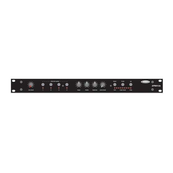
Page 4: Front Panel Features
Whenever power to the SPM412e is turned off or interrupted, output is un-muted. Whenever power to the SPM412e is turned off Channel Select settings are retained in non-volatile memory for or interrupted, Main Level settings (except Mute) are retained in recall when power is turned back on. -
Page 5: Rear Panel Features
(1) Power Cord: The external transformer provides 27 Volts AC (8) Inputs 1~4: These RCA connectors provide the unbalanced to the SPM412e, and is detachable via a 5-pin DIN connector. Stereo Line Inputs for line-level signals (-10dBu or +4dBu). Use Two internal ‘self-resetting’... -
Page 6: Modifications
MODIFICATIONS To access internal modifications, first disconnect power to the unit. Then lay the unit on a flat surface with the front panel facing forward and the top panel facing up. Remove the top panel (eight screws along the sides and rear; one screw centered behind the front panel). Modifications are at the center of the circuit board, starting from the left side (see diagrams below). - Page 7 MODIFICATIONS MIC PRE/POST VCA: Internal jumpers are provided to assign Mic/Line Input signal to the Main Output pre or post VCA (Main Level). From the factory, Mic/Line Input signal is assigned pre-VCA (affected by Main Level). To assign Mic/Line Input signal post-VCA (not affected by Main Level), move jumpers P10 &...
-
Page 8: Remote Control
Infrared and wall-mount remote control is optional for the SPM412e. Remote control affects Channel Select and Main Level (plus mute). Remote control may be added at any time, and does not require the SPM412e to be modified, opened, or removed from a rack. There are two remote control devices: a hand-held Infrared Transmitter and a wall-mount push-button Controller with status indicators &... - Page 9 ) to directly interface to, and control, the SPM412e. To interface a third-party controller to the Translator input, connect the controller output to either the ‘hi’ or ‘lo’ terminal on the SPM412e (depending upon high or low idle signal from the controller) and the controller ground to the SPM412e ‘gnd’ terminal. For reliable operation it is recommended that the SPM412e be located within 10 feet of the third-party controller.
-
Page 10: Applications
15 watts stereo class 2 wiring mono bypass SPM412e Controller Satellite Tape Deck MUTE CHANNEL SELECT MAIN LEVEL Cable CD Player Hostess Stereo Lounge Controller Microphone Amplifier (stereo) Mono... - Page 11 Level for desired overall microphone levels. 3) Connect an automatic or mic/line mixer, such as a BIAMP 7) Connect an optional Controller to the Remote terminals. autoONE or 801 to the Mic/Line Input. Connect a wire across Mount the Controller in a location to accept push-button and/or the ‘Mute’...
-
Page 12: Block Diagram
Channel Level IR3 / low Select Control REMOTE IR2 / high Logic Logic Main Level Reference translator Meter +24V Phantom Power Trim 30dB Mic/Line MIC/LINE Preamp INPUT ▼ Level Signal signal present SPM412e Block Diagram Present ▼ Mute mute Logic... -
Page 13: Specifications
SPECIFICATIONS Frequency Response (20Hz-20kHz @ +4dBu): +0/-0.5dB Total Harmonic Distortion (20Hz-20kHz @ +4dBu): < 0.1% Output Noise (20Hz-20kHz @ nominal levels): < -85dBu Equivalent Input Noise (20Hz-20kHz, 150Ω termination @ Mic/Line Input): < -125dBu Maximum Gain (Mic/Line Input to Main Output): 80dB Input Trim Gain Range: Mic/Line Input (30dB Pad out) -
Page 14: Warranty
WARRANTY BIAMP SYSTEMS IS PLEASED TO EXTEND THE FOLLOWING 5-YEAR LIMITED WARRANTY TO THE ORIGINAL PURCHASER OF THE PROFESSIONAL SOUND EQUIPMENT DESCRIBED IN THIS MANUAL 1. BIAMP Systems warrants to the original purchaser of new THIS WARRANTY IS IN LIEU OF ALL OTHER products that the product will be free from defects in material WARRANTIES, EXPRESS OR IMPLIED.
Need help?
Do you have a question about the SPM412e and is the answer not in the manual?
Questions and answers