Advertisement
Available languages
Available languages
Quick Links
INSTALLATION
THERMOSTAT
This thermostat can replace common residential thermostats and it is
designed for use with most electric, oil or gas heating and air conditioning
THM101B
systems that use low voltage control.
OWNER'S
MANUAL
Note: 2 x "AA " batteries are required for operation. Ensure batteries are installed.
FEATURES
COMPATIBILITY
Read and understand this
Generally, equipment with low voltage control is compatible with the thermostat. For details
manual before installation or
on compatibility of your particular equipment, please call technical support at 1-888-468-6876.
use.
• Easy-to-read LCD display
System Type
• Easy-to-set temperature
Gas - Standing Pilot
settings
• Heat–OFF–Cool and fan
Gas - Electronic Ignition
auto-on switch
ON
Gas - Fire Boiler
COOL
Gas - Millivolt System
Oil - Fire Boiler
Oil - Fire Furnace
Electric Furnace
Electric Air Conditioner
Baseboard Electric Heater (120/240 V)
Heat Pump/Multi-stage equipment
FAN
ON
AUTO
COOL
OFF
HEAT
* NOT COMPATIBLE WITH ANY 120/240 V CIRCUIT.
PAGE 1
INSTALLATION
DISPLAY / BUTTONS
BATTERY INSTALLATION
2 "AA " size batteries are required for operation. The battery symbol (
) will flash when the
1
2
batteries are low. It is recommended that the batteries be replaced at least once a year.
Remove the back cover from the thermostat.
3
Insert the 2 "AA " size batteries into the battery compartment following the correct
polarity as marked.
4
Re-attach the back cover.
ON
HEAT
COOL
NOTE: To select the temperature display format in °C or °F , it must be done immediately
7
following the battery installation.
6
5
SELECTING THE DISPLAY IN C or F
°
°
Immediately following the battery installation, the thermostat will enter the °C/°F
selection mode. The current temperature will appear with the temperature scale
(in °C) flashing.
Use the UP or DOWN button to select the desired temperature scale (in °C or °F).
Otherwise, if no buttons are pressed within 12 seconds, °C will automatically be
selected, and the thermostat will go to its operation mode.
1
ON
COOL
NOTE: Selecting the °C or °F display is a one-time process. Therefore, if you wish to change
it at a later time, you will need to reset the thermostat by pressing the RESET key
above the battery compartment and select °C or °F using the UP or DOWN button.
ATTACHING THE THERMOSTAT TO THE BACK COVER
2
FAN
ON
AUTO
COOL
OFF
HEAT
Attach the thermostat body to the back cover (that is already installed on the wall) by
carefully aligning the two pieces and firmly snapping the 4 latches at the back of the
4
3
thermostat.
PAGE 8
INSTALLATION
The following tools may be required for installation:
(
) screwdriver
Masking tape (To wrap the exposed wires temporarily and labeling the disconnected wires)
Wire stripper/cutter (If necessary, to strip wires)
Power drill with a 3/16" bit (If necessary, to drill holes on the wall)
Level (If necessary, to level the thermostat)
CHOOSING A LOCATION FOR A NEW THERMOSTAT
This thermostat should be mounted:
Approximately 5' (1.5 m) from the floor.
Compatible with thermostat
Near or in a frequently occupied room, preferably on an inside partitioning wall.
Yes
On a section of the wall without pipes or duct-work.
Yes
Some models
This thermostat should NOT be mounted:
Yes
Near a window, on an outside wall, or next to a door leading outside.
Some models
Exposed to direct light or heat from the sun, lamp, fireplace, or other heat radiating
Yes
Yes
objects which may cause false readings.
Yes
Near or in a direct airflow from supply registers and return-air grilles.
No
Near concealed pipes and chimneys.
No
In areas of poor air circulation, such as behind a door or in an alcove.
After choosing a location for the new thermostat, you may arrange to have a
heating contractor install the control wiring for you.
PAGE 2
PAGE 3
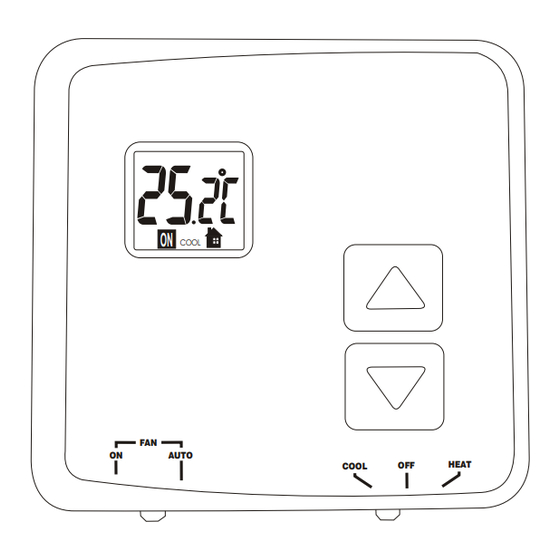
OPERATION
LCD display
"HEAT–OFF–COOL " SWITCH
OFF position:
1
TEMPERATURE DISPLAY
- If the switch is to the OFF position, both the heating and cooling system controls will be
2
LOW BATTERY INDICATOR
turned OFF.
3
2
TEMPERATURE SCALE (
TEMPERATURE SCALE (
°C
°C
or F)
or F)
°
°
HEAT position:
- Slide the switch to the HEAT position to control the heating system.
4
3
TEMPERATURE SETTING MODE
TEMPERATURE SETTING MODE
- The "HEAT" icon will light up when the switch is on the HEAT position.
5
4
CURRENT TEMPERATURE MODE
CURRENT TEMPERATURE MODE
COOL position:
5
6
HEAT OR COOL MODE
HEAT OR COOL MODE
- Slide the switch to the COOL position to control the cooling system.
- The "COOL" icon will light up when the switch is on the COOL position.
7
6
SYSTEM "ON" INDICATOR
SYSTEM "ON" INDICATOR
If the heating or cooling system is turned ON, the "ON" icon will appear and
continue to flash.
button placement
FAN ON/AUTO SWITCH
1
UP BUTTON
For automatic control of the fan, set the FAN ON/AUTO switch to the AUTO position.
In cooling, the fan starts/stops with the cooling equipment. In heating, the fan is
2
DOWN BUTTON
controlled by the heating equipment and usually starts a few minutes after the
heating equipment turns on.
3
"HEAT–OFF–COOL " SWITCH
To turn on the fan manually, set the FAN ON/AUTO switch to the ON position. The fan
4
FAN ON/AUTO SWITCH
will run continuously to improve air ventilation. To return to automatic control, set the
switch to the AUTO position.
PAGE 9
PAGE 10
INSTALLATION
INSTALLATION
REPLACING OLD THERMOSTAT
MOUNTING THE THERMOSTAT BACK COVER
Do not operate the cooling system when outside temperature is below 10
°C
Carefully separate the back cover from the thermostat by disengaging the 4 latches
*
(50 ) to avoid damaging the compressor.
°F
found at the corners on the back of the thermostat. Pull firmly but DO NOT try to pry
open with a screwdriver.
Test the system to make sure that your heating and cooling systems are working
The back cover should be mounted with the large hole on the top.
properly before installation. If either does not work, contact a local heating/air
conditioning service person to fix the problem before installation.
Thread the existing wiring through the large hole from the back and set the back
cover flat on the wall.
TURN OFF POWER to system at the furnace, or at the fuse/circuit breaker panel.
Select two appropriate mounting holes and mark the locations with a pencil. If
necessary, use a level to make sure the thermostat is leveled.
Carefully unpack your new thermostat and mounting plate; save package of screws,
instructions and receipt.
Remove the back cover from the wall and drill two 3/16" holes in the marked screw
positions.
Remove cover from old thermostat. If it does not snap off when pulled firmly from the
bottom, check for a screw used to secure the cover.
Insert the wall anchors into the holes completely. If necessary, use a hammer to
tap-in lightly.
Loosen screws holding thermostat to the wall and lift away the thermostat.
Mount the back cover, with the two screws, to the wall. Make sure the terminals are
on the top-half of the back cover.
Disconnect wires from old thermostat or sub-base. As you disconnect each wire, use
masking tape to label it with the old terminal designation. If there are only two wires,
they don't need to be labeled.
If there is an extra wire that is not connected to your old thermostat, then you won't
need to connect it to the new thermostat.
Take care not to let the wires fall back into the wall or let the ends of the wires touch
one another.
Disengage the latches to
The wires are usually designated 'W', 'Y', 'G', 'R'
separate the back cover
from the thermostat
PAGE 4
PAGE 5
OPERATION
OPERATION
CURRENT TEMPERATURE DISPLAY
TEMPERATURE SETTING
The current room temperature is normally displayed
1
Press the UP or DOWN button once to enter the temperature setting
on the LCD screen. The "
" icon is lit when the
mode. The "
" icon will appear, and the display will now show the
current room temperature is displayed.
current SET temperature flashing.
The displayed temperature range is from 0°C to 60°C
HEAT
(32°F to 140°F). Beyond this, the display will show
2
Press the UP or DOWN button to adjust to the desired set temperature.
either "HI" or "LO".
The resolution of the detected temperature is 0.1°.
The temperature can be set in increments of
The temperature setting range is from
VIEWING THE SET TEMPERATURE
NOTE: Press and hold the button
Pressing either the UP or DOWN button once will
reveal the current SET temperature. The "
" icon
down to accelerate the setting. If no
will appear and the current SET temperature will be
button is pressed within 12 seconds,
flashing.
HEAT
the display will automatically return
to the current temperature display.
DISPLAY AUTO-RETURN
In any setting mode, if no button is pressed within 12
seconds, the display will automatically return to the
RESET
NOTE: There is a built-in delay action to protect the heating and cooling systems.
- When the heating system is ON, it will keep on running for at least 2 minutes even if there
current temperature display.
is a change in the temperature setting.
HE
HE
RESET
HG
HG
- When the heating system is OFF, it will remain OFF for at least 2 minutes before it can
come back ON.
If the thermostat shows an abnormal display or if you
- When the cooling system is ON, it will keep on running for at least 4 minutes even if there
wish to change the temperature scale (°C or °F), use a
is a change in the temperature setting.
pointed object to press the RESET key.
- When the cooling system is OFF, it will remain OFF for at least 4 minutes before it can
come back ON.
PAGE 11
PAGE 12
INSTALLATION
CONNECTING THE WIRES TO THE TERMINALS
TURN OFF POWER to system at the furnace, or at the fuse/circuit breaker before wiring.
Connect the previously labeled wires to the corresponding terminals, matching the
designations. Use a screwdriver to securely fasten the wires onto the terminals. Make sure
the wires do not short-circuit with other terminals.
Depending on your heating/cooling equipment, you may
need to connect 2 to 5 wires to the thermostat.
If your old thermostat has a 'C' wire, please wrap it with
electrician's tape as it is not used with this thermostat.
Wires
If you have both an 'R' and 'Rc' wire, you may connect
them together to the 'R' terminal of the thermostat.
If you are unsure of the connections, or for new
installation, you may refer to the wiring diagrams below.
WIRING DIAGRAM
2-wire heating
4-wire heating/cooling
Heating Relay
LEVEL
Fan Relay
Heating Relay
3-wire heating
Cooling Relay
Metal terminals
Mark the locations
Fan Relay
+
+
with a pencil
Heating Relay
Back cover
PAGE 6
TROUBLESHOOTING
PROBLEM
SOLUTION
LCD screen is blank.
- Check if the batteries are installed correctly.
- Check if the batteries are fresh and of the correct type.
- Press the RESET key on the back of the thermostat above the battery compartment.
The battery symbol (
) is
- This is an indication that the batteries are running low. Replace with fresh alkaline
flashing.
batteries.
- Note: We recommend to have the batteries replaced at least once a year even if the battery
symbol is not flashing.
Heat will not come on.
1) Check and ensure that the thermostat is set to the HEAT mode.
0.5°.
2) Check and ensure that the set temperature is higher than the current (room) temperature.
3) You may have to wait up to 2 minutes before the heat will turn on. The thermostat has a
built-in time delay to prevent undesirable on/off sequences.
5°C to 35°C (41°F to 95°F).
4) After a 2-minute wait, the heating should now be on. Whenever the heating system is
running, the "ON" icon will be flashing.
Heat will not come on but the
1) Check if the furnace switch and/or pilot flame is turned on, as it may have been turned off.
"ON" icon is flashing.
2) Allow several minutes for the heating system to heat up and the fan to activate. Most
heaters will heat up the system for a short while before warm air can be ventilated by the
fan. Also check that the HE/HG setting is set correctly. (Refer to page 7).
3) If the heat still does not come on, check the wiring installation again. (Refer to page 6).
Air conditioning will not come on.
1) Check and ensure that the thermostat is set to the COOL mode.
HEAT
2) Check and ensure that the set temperature is lower than the current (room) temperature.
3) You may have to wait up to 5 minutes before the air conditioning will turn on. The
thermostat has a built-in time delay to protect the air conditioner compressor from
undesirable on/off sequences.
4) After a 5-minute wait, the air conditioning should now be on. Whenever the cooling
system is running, the "ON" icon will be flashing.
Air conditioning will not come on
1) Check if the air conditioning system's main switch is turned on, as it may have been
but the "ON" icon is flashing.
turned off.
2) Wait several minutes for the air conditioning system to activate. If the air conditioning still
does not come on, check the wiring installation again. (Refer to page 6).
PAGE 13
INSTALLATION
SETTING THE FAN OPERATION JUMPER
Depending on your home's heating system, you may need to change the jumper setting for
the fan operation. The jumper is located above the battery compartment.
HG - Use this setting for gas or oil-fired furnaces. This setting allows the fan
operation to be controlled by the heating system; not the thermostat. This is the
correct setting for most systems.
Wall
HE - Use this setting for electric heating systems. With this setting, the thermostat
will turn on the fan immediately with the heating system.
The jumper is pre-installed in the 'HG' position as a factory default. So there is no need to
Metal
change the jumper if this is the correct setting.
terminals
To change the jumper setting, pull out the small black rectangular block and align it to the
Back cover
new position and push in fully.
HE
HE
HG
HG
PAGE 7
LIMITED ONE-YEAR WARRANTY
UPM warrants this product, excluding battery, to be free from defects in the materials or workmanship, under normal use and
service, for a period of one
(1)
year from the date of purchase by the consumer.
If, at any time during the warranty period, the product is defective or malfunctions, UPM shall repair or replace it (at UPM's
discretion) within a reasonable period of time.
If the product is defective,
(i)
return it, with a dated proof of purchase, to the retailer from which you purchased it, or
(ii)
package it carefully, along with a dated proof of purchase and a short description of the malfunction, and mail it, postage
prepaid, to the following address:
UPM Marketing Inc.
Return Goods
Unit 10B - 250 Shields Court
Markham, Ontario
L3R 9W7
This warranty does not cover removal or reinstallation costs. This warranty shall not apply if it is shown by UPM that the defect or
malfunction was caused by damage which occurred while the product was in the possession of the consumer.
UPM's sole responsibility shall be to repair or replace the product within the terms stated above. UPM SHALL NOT BE LIABLE
FOR ANY LOSS OR DAMAGE OF ANY KIND, INCLUDING ANY INCIDENTAL OR CONSEQUENTIAL DAMAGES RESULTING,
DIRECTLY OR INDIRECTL Y, FROM ANY BREACH OF ANY WARRANTY , EXPRESS OR IMPLIED, OR ANY OTHER FAILURE OF
THIS PRODUCT. Some states do not allow the exclusion or limitation of incidental or consequential damages, so this limitation
may not apply to you.
THIS WARRANTY IS THE ONLY EXPRESS WARRANTY UPM MAKES ON THIS PRODUCT . THE DURATION OF ANY IMPLIED
WARRANTIES, INCLUDING THE WARRANTIES OF MERCHANTABILITY AND FITNESS FOR A PARTICULAR PURPOSE, IS
HEREBY LIMITED TO THE ONE YEAR DURATION OF THIS WARRANTY . Some states do not allow limitations on how long an
implied warranty lasts, so the above limitation may not apply to you.
This warranty gives you specific legal rights, and you may have other rights which may vary from state to state.
If you have any questions concerning this warranty, please write to:
UPM Marketing Inc.
Customer Service Department
Unit 10B - 250 Shields Court
Markham, Ontario
L3R 9W7
Or call 1-888-GO-TO-UPM (1-888-468-6876), Monday to Friday, from 9:00am to 5:00pm eastern.
PAGE 14
Advertisement

Related Manuals for UPM THM101B


Summary of Contents for UPM THM101B
- Page 1 “ON” icon will be flashing. This warranty does not cover removal or reinstallation costs. This warranty shall not apply if it is shown by UPM that the defect or - The “COOL” icon will light up when the switch is on the COOL position.
- Page 2 FONCTIONNEMENT DÉPANNAGE GARANTIE LIMITÉE D’UN AN affichage à CL UPM garantit que ce produit, à l'exception des piles, est exempt de tout défaut matériel et de fabrication et qu'il est couvert par une RÉGLAGE DE LA TEMPÉRATURE PROBLÈME SOLUTION INSTALLATION DES PILES COMMUTATEUR CHAUFFAGE-ARRÊT-CLIMATISATION...
Need help?
Do you have a question about the THM101B and is the answer not in the manual?
Questions and answers