
Related Manuals for Filser Electronic ATR 57 COM


Summary of Contents for Filser Electronic ATR 57 COM
- Page 1 Filser Electronic GmbH Gewerbestraße 2 86875 Waal ATR 57 COM VHF Transceiver Installation User manual Ver. 1.5, Date: May 01 Page 1...
-
Page 2: Table Of Contents
Filser Electronic GmbH Gewerbestraße 2 86875 Waal Contents 1 GENERAL INFORMATION ............4 Introduction ................4 1.2 Purpose of this equipment............4 1.3 Specification ................. 5 1.4 Manufacturer ................5 2 INSTALLATION.................6 2.1 General ..................6 2.2 Pre-installation check..............6 2.3 Mechanical Panel installation ............6 2.4 Installation wiring ................ -
Page 3: 86875 Waal
Filser Electronic GmbH Gewerbestraße 2 86875 Waal 3.8 Automatic frequency control ............12 3.9 Transmitting mode..............13 3.10 Receiving indication ..............13 EuroCAE EC-Type Approval Certificate Ecanadian Certificate ..16 EC-Type Approval Certificate Ecanadian Certificate .....17 Ecanadian Certificate.................18 Page 3... -
Page 4: General Information
Filser Electronic GmbH Gewerbestraße 2 86875 Waal General Information 1.1 Introduction This ATR 57 Handbook describes the VHF Communication transceiver with following sections. 1. General Information 2. Installation 3. Operating Instructions 1.2 Purpose of this equipment The Filser ATR 57 is a VHF Communication transceiver covering the aeronautical radio frequency range from 118,00MHz to 136,975 MHz in 25 KHz increments with 720 channels. -
Page 5: Specification
Filser Electronic GmbH Gewerbestraße 2 86875 Waal 1.3 Specification Frequency range: 118,000 ..136,975 MHz Channels: Channel spacing: 25 kHz Modulation: AM DSB, 70% modulation Operation modus: alternate talking on one frequency RF-output power: > 1 Watt NF-output power: 1 Watt... -
Page 6: Installation
Filser Electronic GmbH Gewerbestraße 2 86875 Waal Installation 2.1 General Installation of the ATR 57 VHF Communication transceiver depends on the type of aircraft and equipment involved. The instruction given in this section are therefor only general applicable. 2.2 Pre-installation check... -
Page 7: Microphone Connection
Filser Electronic GmbH Gewerbestraße 2 86875 Waal 2.5 Microphone connection The ATR57 has two microphone inputs :Mic 1 and Mic 2. Ø Mic 1 input for Electret microphone or dynamic microphone with preamplifier (50 mV to 2Vpp) adjustable with the Mic Level control. -
Page 8: Intercom Mode
Filser Electronic GmbH Gewerbestraße 2 86875 Waal 2.6 Intercom mode With Intercom two crew members can talk to each other over the ATR 57 system. This of communication takes place only internally, there is no transmission. A special feature is the VOX (Voice Operated Transmission(x)). The Intercom is opened only if one of the crew members is speaking. -
Page 9: 86875 Waal
Filser Electronic GmbH Gewerbestraße 2 86875 Waal Installation wiring diagram for glider installation Page 9... -
Page 10: 86875 Waal
Filser Electronic GmbH Gewerbestraße 2 86875 Waal Installation wiring diagram for double installation with intercom Page 10... -
Page 11: Operation Instructions
Filser Electronic GmbH Gewerbestraße 2 86875 Waal Operation Instructions 3.1 Turn on The „ON-OFF“-switch (2) is mounted on the left side of the unit. The radio is active, when the switch position is in „ON“ (upper position). 3.2 Volume control Push the VOL-SQ button once to get into the Volume mode (Display shows VOL: 01 to 33). -
Page 12: Memory Selector
Filser Electronic GmbH Gewerbestraße 2 86875 Waal Note: The Volume control described in 3.2 adjusts only the received signal and not the Intercom level. 3.5 Memory selector The memory selector MEM (7) is located in the upper middle of the unit. -
Page 13: Transmitting Mode
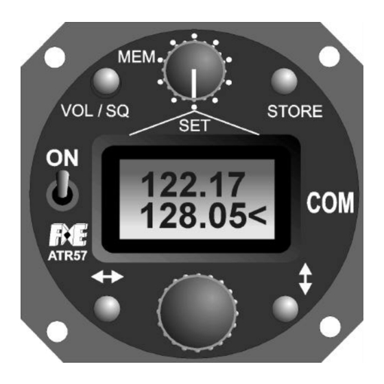
Filser Electronic GmbH Gewerbestraße 2 86875 Waal In this case the ATR 57 is not working properly and must be returned to the manufacturer. Notice: Sometimes the "-" may be displayed, but it disappears when the frequency is changed or the device is switched off and on. This can be due to strong noise from outside the ATR 57. - Page 14 Filser Electronic GmbH Gewerbestraße 2 86875 Waal ATR 57 Operating Controls 1. Volume / Squelch push-button 2. ON / OFF switch 3. MHz / kHz push-button 4. Tuningknob for Volume, Squelch, VOX and standby frequency 5. Change selected frequency to active frequency 6.
- Page 15 Filser Electronic GmbH Gewerbestraße 2 86875 Waal ATR 57 Display 8. "B" Low-Battery display, shown when voltage is < 10,5V 9. "><" changing MHz or kHz range 10. MHz-range of standby frequency 11. kHz-range of standby frequency 12. "-" shown at lost of transmitting or receiving frequency (active frequency) 13.
-
Page 16: Eurocae Ec-Type Approval Certificate Ecanadian Certificate
Filser Electronic GmbH Gewerbestraße 2 86875 Waal EuroCAE Page 16... -
Page 17: Ec-Type Approval Certificate Ecanadian Certificate
Filser Electronic GmbH Gewerbestraße 2 86875 Waal EC-Type Approval Certificate Page 17... -
Page 18: Ecanadian Certificate
Filser Electronic GmbH Gewerbestraße 2 86875 Waal Ecanadian Certificate Page 18... - Page 19 Filser Electronic GmbH Gewerbestraße 2 86875 Waal Page 19...
Need help?
Do you have a question about the ATR 57 COM and is the answer not in the manual?
Questions and answers