
Related Manuals for FMUser 500W


Summary of Contents for FMUser 500W
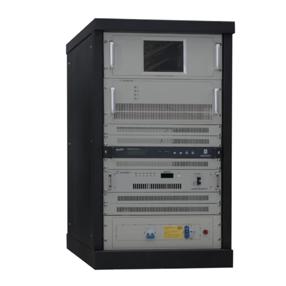
- Page 1 Fmuser.org 500W and 1KW Analog TV Transmitter User’s Manual www.fmuser.org...
- Page 2 Overview: This product is the all solid-state Single-channel TV Transmitter, it adopts professional TV exciter, and it can use the single/duel exciter configuration, switching automatically. This transmitter has a variety of linear and non-linear pre-correction function, carrier frequency offset, and precision bias (with external precision reference source) function.
- Page 3 The fan is built-in the chassis, the transmitter has a compact structure and a beautiful shape. Technical Specifications: Overall performances: 1. Working frequencyÿ UHF 13~48 Channel arbitrary choice 2. Output powerÿ 500W/1KW 3. Output impedanceÿ 4. VSWR of output load impedanceÿ ≤1.12 5. Inter-modulation distortionÿ ≤-50dB 6. Useless transmissionÿ...
- Page 4 5. Luminance nonlinearÿ ≤10% 6. Group delayÿ ≤±60ns 7. Signal-to-clutter ration of low frequency period interference: ≥50dB Sound performance: 1. Audio input levelÿ 0dBm±6dB 2. Audio input impedanceÿ (imbalance) (Balance) 3. Maximum frequency deviationÿ ±50KHz 4. Harmonic distortionÿ ≤1% 5.
- Page 5 Please notice thisÿ 1. Read safety notice first0 2. A 50 Ohm dummy load or antenna and cable must be connected before turning power on, Avoid water going into the connecters or the cable. 3. Exciter’s operating frequency must be set to the same frequency of the transmitter.
- Page 6 Contents Safety Notice-----------------------------------------------------------------4 Special Reminds-------------------------------------------------------------4 1. Power on Sequence ------------------------------------------------------5 2. Control System Introduction ------------------------------------------7 3. Operation Instructions -------------------------------------------------10 www.fmuser.org...
-
Page 7: Safety Notice
Safety Notice 1.1 Please read the following safety points, in order to avoid accidents and prevent connectors to be broken. 1.2 Only the qualified maintenance workers can operate the device. P ÿ revent from fire and body injury ÿ... - Page 8 Please notice this: 1 . The 50© dummy load or antenna and cable must be rightly connected, carefully keep away water into connecters and cable. 2 . The design of the transmitter is an integral structure. It gathers the whole display operation on the LCD display screen, completely realized the software, the operation is very simple and rapidly.
- Page 9 Fix it correctly to keep it radiating well. Please don’t disassemble and repair by yourself when it’s broken ÿ ÿ ÿ ÿ ÿ ÿ ÿ ÿ ÿ ÿ ÿ ÿ ÿ ÿ ÿ ÿ ÿ down. Please send to the professional service department to solve ÿ...
- Page 10 Overview This series TV transmitter is an excellent product that owns the highest and newest technology. The whole machine adopts the latest TV signal processing technology. www.fmuser.org...
- Page 11 Display This series TV transmitter displays the operation parameters of the modulator on large LCD screen in real time Its particular FOUR_KEY design, you can conveniently and fast modify, view the operation parameter and the statement of the transmitter in any time.
-
Page 12: Technical Specifications
Technical Specifications . Technical Specifications 1 . Power Supply % AC220V±10% 50Hz % AC110V±20% 50Hz % FULL RANGE 2 . Heat Abstraction Forced Convection 3 . Output Powerÿ Adjustable Continuous to rate power 4 . Output Impedance 5 . RF Output Linker... -
Page 13: Panel Function Description
Panel Function Description Front panel picture 1 —Ampliferÿ 2—MODULATER 3 —SWITCH POWER SUPPLYÿ 4—POWER SWITCH www.fmuser.org... -
Page 14: Rear Panel Function Description
20 REAR panel function description 1 — AC Socket for amplifer Fuse 5A 2 — RF input Port 3— RF Output Port 4 — AV Input 5 — AC Socket for modulator www.fmuser.org... - Page 15 6 — DC controling line AC Connector 220V DC Connector red=”+” black= “-” 0 PA Front panel function description 1 —POWER: power supply OKÿ 2—MODULATER: Modulater POWER supply OK 3—VOLTAGE: PA VOLTAGE over alarm; 4—CURRENT: PA Current over alarm;...
- Page 16 6—RF : RF power over alarm. 7 —LCD display Screen 8 —key-press UP and LEFT light cursor 9 —key-press ENTER 10 —key-press DOWN and RIGHT light cursor 11—Power Switch www.fmuser.org...
-
Page 17: Special Tips
Special Tips l Turn on RF power after setting all other parameters l CAN address of exciters and amplifier modules are set in factory, please do not change it. l The transmitter is AGC controlled when CAN AGE in exciter is ENABLED. -
Page 18: Power On Sequence
1 Power On Sequence 1.1 Check all connections l Combiner to dummy load or antenna l Amplifier modules to combiner l Divider to amplifier modules l Switcher to divider l Exciters to switcher l Main exciter to backup exciter... - Page 19 1.4 Set CCU parameters l Turn off RF Switch: RF Switch = OFF l Power Percentage: 0%--100% l Period Control If period control is needed, set three periods first and then enable Period Control (Period Control =Enabled). If period control is not needed, just disable Period Control (Period Control = Disabled).
- Page 20 2 System Control Introduction 2.1 Main Control Function l Data collection and display from 6 amplifiers which include voltage, current, temperature, running status, forward power and reflect power. l Combiner data acquisition and display which include temperature, forward power and reflect power.
- Page 21 Other manufacturer’s exciter can be used but can not be connected on the internal CAN bus network not matter there is a CAN interface or not due to the restriction of the internal communication protocol.
- Page 22 2.3 (CCU) Remote Control CCU has a RS232 interface that can connect to a computer for the remote control purpose. The remote computer can read the following datum: l Equipments’ type and profile, such as nominal power, frequency, number of amplifier modules, maximum power of amplifier module and number of exciters.
-
Page 23: Rf Output Control
The Automatic Power Control function is enabled when exciter’s CAN AGC is set to enabled, otherwise the system is in Manual Power Control mode. In manual power control mode, the output power is not controlled by CCU (CCU can not control exciter’s power). So, the machine’s output power would be fluctuated with the temperature or other factors change. - Page 24 2.6 System Protection AIn automatic control mode, if RF output power is not able to reach to setting power, it may cause by: l Combiner temperature is above 70. l Combiner’s reflect power is above the warning value (more than 2% of the machine’s nominal power).
-
Page 25: General Descriptions
3 CCU Menu Operation 3.1 General Descriptions The CCU LCD display is divided into 4 functional pages: Main Page, Status Page, Time Page and Remote Page. Touch screen is used to get through all functions. Three hidden buttons is used to set and select parameters. When click on the displayed setting parameter, buttons are visible and setting parameter is displayed in reverse video indicating the parameter is in editing. -
Page 26: System Boot Up
System Boot up During the system boot up, company logo is displayed until system boot up finish. After system booting up, it enters to Main Page. 3.3 MAIN PAGE Power Forward: forward power, display only Percentage: forward percentage setting, setting parameter. - Page 27 This page display running status of all components. Click on status block can enter to corresponding component page to see its detail information. Different color of each component indicate its running status, it is defined as follow: Blueÿ Yellowÿ...
- Page 28 Last Reboot Reason: --No reboot --Forward power is too high --Reflect power is too high --The temperature of combiner is too high --Unbalanced power is too high 3.4.2 Combiner Working Status Forward Power: Combiner Forward Power Reflect Power: Combiner Reflect Power Temperature: Combiner Temperature www.fmuser.org...
- Page 29 Module forward power: The Forward Power of each amplifier 3.4.3 Exciter Working Status Forward Powerÿ Exciter Forward Power Reflect Powerÿ Exciter Reflect Power Frequency: Exciter working frequency On Air: ON---Exciter’s RF power turned on OFF—Exciter’s RF turned off Lÿ...
- Page 30 3.4.4 Power Amplifier Working Status Status: Working—Power Amplifier is working normally Booting--Power Amplifier is booting Blocked--Power Amplifier is on protecting status; Because of the self-protection, it would be rebooted and turns on the RF in 10 seconds when extremely case occurs.
- Page 31 3.5 Time & Period Control Date: Set date or display date. The format is: YY/MM/DD DAY Time: Set time or display time. The format is: HH:MM:SS Time Control: Enabled: Time Period Control is enabled. Disabled: Time Period Control is disabled.
-
Page 32: Remote Control
3.6 Remote control Baud rate: Setting remote communications baud rate. Address: Setting remote communications address. Remote: Enabled — parameters can only be changed remotely. Disabled—parameters can be changed only locally. www.fmuser.org...
Need help?
Do you have a question about the 500W and is the answer not in the manual?
Questions and answers