Table of Contents
Advertisement
Advertisement
Table of Contents

Subscribe to Our Youtube Channel
Related Manuals for St. Croix SCF 050

Summary of Contents for St. Croix SCF 050
- Page 1 Installation & Operations Manual SCF 050 FURNACE SCF-Revolution Manual...
-
Page 2: Table Of Contents
TABLE OF CONTENTS General Information ........................4 Installation Check List ......................5 Furnace Layout Diagram ......................6 Furnace Dimensions, Location & Clearances ................ 7-8 Exhaust Venting........................10 Venting - Approved Materials .................. 10 Venting-Typical PL Vent Components..............11 Venting - Determining Materials ................12 Venting - Termination Requirements................. - Page 3 Combustion Air Damper – Location and Adjustments..........29-33 Thermostat Control & Pilot Settings................34 SCF-050 Maintenance ....................34 St. Croix Clinker Theory................34 Clinker/Ash Removal..................25 Daily Maintenance ....................36-38 Periodic Maintenance....................39-41 Yearly Maintenance ....................42-43 Safe Operation ......................43 Wiring Schematic......................44 Electrical Layout......................
-
Page 4: General Information
Save This Installation & Operations Manual GENERAL INFORMATION SAFETY PRECAUTIONS SAFETY NOTICE: The furnace must be properly installed in order to prevent the possibility of a house fire! These installation instructions must be strictly observed! The Maintenance schedule must be followed as described in this manual. Failure to follow instructions may result in property damage, bodily injury or even death. -
Page 5: Installation Check List
BEFORE INSTALLATION THOROUGHLY READ AND UNDERSTAND THIS MANUAL SAFETY NOTICE PLEASE READ THE ENTIRE MANUAL BEFORE INSTALLING AND USING YOUR NEW FURNACE. FAILURE TO FOLLOW INSTRUCTIONS MAY RESULT IN POPERTY DAMAGE, BODILY INJURY, OR EVEN DEATH. INSTALLATION CHECK LIST FOR USE IN THE U.S. AND CANADA, MOBILE HOME APPROVED CHECK WITH LOCAL AUTHORITIES AND OBTAIN NEEDED PERMITS WE RECOMMEND INSTALLATION BY A QUALIFIED PROFESSIONAL. -
Page 6: Furnace Layout Diagram
The SCF-050 has a large Heat Exchange system, allowing for more heat to be exchanged. The burn system used in the furnace is the St. Croix Patent Pending “Clinker Removal System”. This burn pot allows the clinker to be removed without loosing the fire in the pot. This eliminates the need of having to constantly re-light the furnace after removing the clinker. -
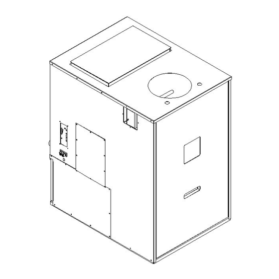
Page 7: Furnace Dimensions
Furnace Dimensions Figure 2 Furnace location When finding a location to install the furnace, several things need to be kept in mind. Consider the following things: Service Access, Venting, Return air Duct, Supply air Duct and Electrical. Service Access. The front panel is removable to allow access to the ash pan and the firebox for regular maintenance. - Page 8 Clearances & Access for Service & Maintenance Figure 3 FLOOR PROTECTION - The furnace should be installed on a non-combustible surface extending 16” in front of the unit. LEFT SIDE – Minimum clearance to combustibles on the right side of the furnace is 2” ACCESS FOR SERVICE AND MAINTENANCE –...
- Page 9 Caution INSTALLATION IS TO BE PERFORMED BY A QUALIFIED INSTALLER OR DEALER. ADHERE TO ALL CLEARANCES SPECIFIED BY THE MANUFACTURER OF THE VENTING SYSTEM USED. ADHERE CLEARANCES SPECIFIED INSTALLATION INSTRUCTIONS OF THIS FURNACE. THIS FURNACE USES A POSITIVE PRESSURE VENTING SYSTEM. DO NOT INSTALL A FLUE DAMPER IN THE EXHAUST SYSTEM OF UNIT DO NOT CONNECT THIS FURNACE TO A CHIMNEY SYSTEM THAT IS CONNECTED TO ANOTHER APPLIANCE.
-
Page 10: Venting: Approved Materials
VENTING: APPROVED MATERIALS The Furnace requires a venting system approved for pellet Furnaces by a certified testing lab. Approved pellet Furnace venting materials are: 1) PL vent, a double wall vent with a stainless steel liner; and 2) Single wall rigid or flexible stainless steel pipe. PL Vent and Single wall vent is available through manufacturers such as: Energy Vent LTD, James A. - Page 11 TYPICAL PL VENT COMPONENTS RAIN CAP VERTICAL OR WALL THIMBLE CHIMNEY SUPPORT BRACKET HORIZONTAL ADAPTER ADJUSTABLE LENGTH SINGLE TEE SINGLE REDUCTION DOUBLE TEE PIPE w/TEE CAP TEE w/TEE CAP w/TEE CAP PIPE ADAPTER INCREASER ELBOW ELBOW SCF-Revolution Manual...
-
Page 12: Venting: Determining Materials
VENTING: DETERMINING MATERIALS TYPE OF MATERIALS: 1. PL Vent must be used. 2. Exception: Single wall stainless steel may be used inside an existing chimney. (No clearances to combustibles are needed on single wall stainless steel adaptors, rigid or flex pipe installed within a chimney.) 3. -
Page 13: Venting: Termination Requirements
VENTING: TERMINATION REQUIREMENTS In determining optimum vent termination, carefully evaluate external conditions especially when venting directly through a wall. Since you must deal with odors, gases, and fly ash, consider aesthetics, prevailing winds, distances from air inlets and combustibles, location of adjacent structures and any code requirements. - Page 14 b. With Outside Air Connected to the unit. In this manner the appliance is a Direct Vent Appliance (sealed Combustion System) as listed in NFPA 211-6. 3.3.3.2 Direct Vent Appliance (Sealed Combustion System Appliance) A system consisting of an appliance, combustion air and flue gas connections between the appliance and the outside atmosphere, and a vent cap supplied by the manufacturer, and constructed so that all the air for combustion is obtained from the outside atmosphere and all flue gases are discharged to the outside atmosphere.
-
Page 15: Venting: Termination Clearance Requirements
VENTING: TERMINATION CLEARANCE REQUIREMENTS Figure 5 THE EXHAUST TERMINATION LOCATION MUST BE AT LEAST 1’ (305 mm) ABOVE the ground level 7’ (2.1 m) FROM a public walkway 1’ (305 mm) FROM The wall penetration point 3’ (915mm) FROM a gas meter/regulator assembly 2’... -
Page 16: Venting Into An Existing Chimney
Venting into an Existing Chimney Figure 6 The Furnace may be connected to an existing Class A chimney or a masonry chimney which meets the minimum requirements of NFPA 211. 1. If the Furnace’s exhaust is connected to a masonry chimney, the masonry chimney must be free of cracks that could leak exhaust gases or fly ash. -
Page 17: Combustion Air
COMBUSTION AIR 1. Under certain conditions it is recommended that the Furnace be connected to an outside source of combustion air to improve Furnace performance. Flexible metal hose, such as ClevFlex, or rigid metal pipe, (conduit), must be connected around (NOT INSIDE) the combustion air inlet tube (Figure 11A). -
Page 18: Connecting To Existing Duct Work
Central furnace or of the SCF 050. Running both furnaces at the same time should not cause any nuisance tripping of the High Limits in either unit. -
Page 19: Fan Limit Control
Blower Specs The Blower is a 2-Speed blower. (600 – 800 CFM) When connecting this unit to a duct system, the high speed should be used. If the Furnace is to be used as a stand- alone shop heater, the option is available to select the 600 CFM setting or the 800 CFM setting. -
Page 20: Mobile Home Installation
Mobile Home Installation Unit must be installed in accordance with the: Manufactured Home and Safety Standard (HUD), CFR 3280, Part 24 The Furnace has been tested and listed for mobile home installations. In addition to all previously detailed requirements, mobile home installations must observe the following: WARNING: DO NOT INSTALL IN A SLEEPING ROOM. -
Page 21: Thermostat Hook-Up
4. Permanently bolt the Furnace to the floor. 5. Electrically ground the Furnace and pedestal to the metal chassis of the home. Use a number eight, (8) gauge or larger copper wire. 6. Maintain an effective vapor barrier at location where PL vent exits the structure. 7. -
Page 22: Scf-050 Operation
SCF-050 OPERATION CAUTION: Operate this unit only with the fuel hopper lid closed. Failure to do so may result in emission of products of combustion from the hopper under certain conditions. Maintain hopper seal in good condition INSTALLATION CHECK Proper installation is essential for safety, effective Operation, Warranty Coverage, Insurance requirements and to meet Local Building Codes. -
Page 23: Approved Fuels
– APPROVED FUELS Corn, Pellets, Wheat, Rye, Cherry Pits & Distiller’s Grain Pellets. Corn, Wheat, Rye, Distiller’s Grain must be 15% or less moisture content. The keys to satisfactory performance are: proper operation of the stove, diligent maintenance and burning only dry, clean, quality corn, wheat &... - Page 24 To burn Pellets, Cherry Pits & Distiller’s Grain Pellets detach the side shields by loosening the 2 screws holding the shield in place and lift off of the burnpot. Do not discard this part, but save it for future use in the event you switch back to burning corn, wheat or rye.
-
Page 25: Operating Instructions
OPERATING INSTRUCTIONS A different type of heater. The SCF-050 is a furnace. FOLLOW THESE OPERATING INSTRUCTIONS EXACTLY AS STATED TO ENSURE SAFE AND RELIABLE OPERATION. 1. Carefully read this “Operation and Maintenance” manual in its entirety BEFORE lighting your Furnace for the first time. 2. -
Page 26: Control Board Features
Control Board Features The Control Board controls all functions of the furnace by monitoring sensors that are in the system. These sensors serve 2 purposes. a. General Operation of the Furnace. b. Safety Features, to shut the unit down in the event the sensors detect a problem in the unit. -
Page 27: Pre-Lighting & Lighting Instructions
2. The On/Off button (2) turns the Furnace On and Off. It will also reset the board after the board has sensed a problem and is flashing a Diagnostic code. 3. The auger button (3) will allow the customer to manually auger fuel into the burn pot on start up when needed. -
Page 28: Lighting Your Furnace
WARNING: - Risk of Fire. -Do not operate with the Firebox door or Ash Removal doors open -Do not store Fuel or other Combustible material within marked Installation Clearances. -Inspect and Clean Flues and Chimneys regularly. Danger: Risk Of Fire or Explosion -Do not burn Garbage, Gasoline, Drain Oil or other Flammable Liquids. -
Page 29: Shutting Off The Furnace
b. When the board senses the Vacuum switch the exhaust fan speed drops to the #1 setting and runs for 5 minutes. c. After 5 minutes the board checks for “Proof of Fire” and starts feeding fuel on the #1 setting. (See section on Diagnostic Features on page27) If the board senses P.O.F. -
Page 30: Safety Features
The Diagnostic Lights flash as follows: 1. The Proof of Fire switch. This switch will sense the temperature of the Exhaust rising during start up. If the Exhaust temperature does not reach 110 degrees F, or if during use the temperature drops below 110 degrees F, the Furnace will go into “Internal Alarm”... -
Page 31: Combustion Air Damper
the Furnace is put back in service, (Defective Room Fan, dirty Room Fan, dirty Return Air Filter, defective Fan Limit Control or possibly a bad Control Board) 2. Proof of Fire switch also called the P.O.F. This senses the temperature rise in the exhaust system. - Page 32 When burning corn, wheat, rye & Distiller’s Grain pellets the burn pot should be “BALANCED”. This means the fuel that is being augered into the burn pot rapidly turns into glowing coals. If you see a lot of unburned fuel in the pot, an adjustment may be needed.
- Page 33 If you experience problems adjusting the Furnace during the Break-In Period, contact your dealer. The figure below may be used to gage the approximate damper setting when making an adjustment. Some chimney systems will fall outside the norm, for example, a chimney with excessive draft or one with a long horizontal run. In dealing with technical support, the terminology listed in figure 16 may be used to clarify where your damper needs to be set.
- Page 34 Terminology used when burning Grain ( corn, wheat, rye & Distiller’s Grain) 1. Balanced burn pot. This means the rapidly turns into red-hot coals once it is in the burn pot. 2. Lag time. This is the time it takes for the corn, wheat or rye to start burning and the burn pot to become balanced.
- Page 35 e. Advance the heat setting to #5 and let the Furnace burn at this setting for ½ an hour. Check the burn pot to see if it is balanced. A small damper adjustment might need to be made at this time to make sure the “Lag time” isn’t too long. Remember: Only turn the setscrew one 1/2 turn clockwise to open the damper.
-
Page 36: Thermostat Control & Pilot Settings
The Furnace may be controlled with a thermostat to help maintain a more constant temperature. A Multi-Fuel furnace, such as the SCF 050, will be a little slower in reacting to a thermostat than the typical Gas, Electric or Oil fired furnace. With this in mind we have incorporated 3 Pilot settings on the control board (See Point 5 on Page 25). -
Page 37: Clinker/Ash Removal
Once a clinker/ash has formed in the burn pot, it must be removed or the Furnace will go out. The St. Croix Burn system is designed to remove the clinker/ash without loosing the fire in the burn pot. It is a 3-part system. -
Page 38: Daily Maintenance
CAUTION: THE DOOR AND FRONT PART OF THE FURNACE WILL BE HOT. DO NOT TOUCH ANY PART OF THE FURNACE THAT IS HOT! Daily Maintenance Example of Schedule for dropping Clinkers and Ash from burn pot: This may be required more than once a day, depending on the burn rate of the Furnace and the quality of Corn, wheat or rye or pellets used. - Page 39 1. The coal Rake. The first step is to push the coal rake in and shave the coals off the top of the clinker. Once this is done open the door and add a ¼ cup of pellets on top of the coals (See figure 18). To push in the Coal rake, use the Rod Handle tool shown in figure 20 on page 39.
- Page 40 4. The control board. Set the heat setting to #1 for a few seconds and return to the setting it was on. This initiates the time delay for dropping the clinker. 5. Dropping the coals back into the burn pot. At this time pull the coal rake back out of the burn pot to drop the coals in the pot.
-
Page 41: Periodic Maintenance
Periodic Maintenance CAUTION: Periodic maintenance should only be done while the Furnace is shut off and cold. 1. Ashpan. Empty the ash pan when it appears full (approximately once a week). The frequency of cleaning the ash pan will depend on the quality and amount of fuel being used. - Page 42 3. Clean-Out Ports. The Furnace has 3 Exhaust Cleanout Ports located in the LEFT AND RIGHT lower corners of the firebox and behind the Ashpan. Remove covers and clean regularly. Figure 21 Frequency of cleaning depends on the amount of fuel being burnt and the quality of the Corn, wheat, rye or pellets.
- Page 43 Baffle Removal To remove the baffle, lift the back of the baffle up to clear the inner back of the Furnace and slide towards the front of the Furnace. The baffle will slide out of the keyhole slots and drop down. When putting the baffle back in the Furnace, make sure the screws are in the keyhole slots and the back of the baffle is lifted...
-
Page 44: Yearly Maintenance
Many dealers offer a Service Contract that will cover Yearly Maintenance. Contact your St. Croix Dealer for assistance in maintaining your Furnace in top condition. Yearly Maintenance Yearly maintenance is designed to assure safe operation, prolong the life of the Furnace and help preserve its aesthetic appeal. -
Page 45: Safe Operation
4. The exhaust fan should be removed and cleaned with compressed air annually. Call dealer for this service. Annual oiling of the motors is not needed. 5. The Convection Blower should be removed and cleaned with compressed air annually. There are 2 oil ports on the motor. Fall Startup. -
Page 46: Wiring Schematic
Wiring Schematic Figure 24 The Electrical Rating of this furnace is: 120 Volt, 60 Hz, 4 AMP. The minimum recommended circuit is 15 Amp. A dedicated circuit for the furnace is recommended. SCF-050 Manual... -
Page 47: Electrical Layout
CAUTION: The electrical components of the Furnace are not owner serviceable. Call your dealer for proper diagnosis of electrical problems and service to those components. Electrical Layout Figure 25 Fan Limit Control Control Board Convection Blower Thermostat Wiring Terminal Combustion Blower Wiring Terminal Block (Inside Cabinet) Proof of Fire Switch 2-Speed Blower Rocker Switch... - Page 48 Additional Canadian Installation requirements. The fans of this Furnace may cause a negative pressure area in the room where this Furnace is installed. If the Furnace is not connected to a Return Air duct system in the house, provision should be made to provide make-up air to the unit. It is recommended to provide opening equal to 120 Square inches for Return Air to the Furnace room.
-
Page 49: Installation
Additional Canadian Requirements for Supplementary (Add-On) Furnaces. (See label on the inside front panel of the furnace for additional information) DO NOT USE DUCT ELBOWS HAVING AN INSIDE RADIUS OF LESS THAN 6“(150mm) ON THE FURNACES. DO NOT CONNECT DUCTWORKSO THAT A REVERSE FLOW IS POSSIBLE. OPERATE THE (GAS, OIL OR ELECTRIC) FURNACE PERIODICALLY TO ENSURE THAT IT WILL OPERATE SATISFACTORILY WHEN NEEDED. -
Page 50: Operation
TROUBLESHOOTING & FRQUENTLY ASKED QUESTIONS The Furnace is very trouble free in operation when properly maintained and quality pellets are used. When the Furnace fails to operate properly, troubleshooting by the operator of the Furnace is limited. Please read the following guide for answers to frequently asked questions When first starting the Furnace remember the auger tube is empty, which will delay feeding fuel to the burn pot. - Page 51 Solution: If the fire is out, re-light the Furnace. If the fire is still burning make sure all doors are securely latched and hold down the On/Off button (approximately 5 seconds) until Furnace starts up again. This will re-start the Furnace in the start-up program.
- Page 52 Replace with a 250 Volt, 5 Amp fuse. 10. Why is my glass dirty? Normal operation of your St. Croix Furnace will produce a white build- up on the glass that wipes off with a dry paper towel. However extended burning on the low setting only will produce a light tan color.
- Page 53 The default Pilot setting has an On Time of 2.5 seconds. The #1 LED light indicates the default pilot setting. This setting requires little fine tuning. Pressing the Feed Trim button once will turn the #1 and #4 LED lights on at the same time. This reduces the On Time to 2.0 seconds.
- Page 54 12. How do I adjust the draft for the Pilot settings (#1 setting)? Not all fuel burns at the same rate. The moisture content of corn, wheat or rye greatly influences how it burns. Burning Pellets requires adjustments to the low burn to prevent Creosote from forming. Following is a description of the function of the Fan Trim button.
-
Page 55: Warranty
SCF-050 WARRANTY The Furnace manufactured by Even Temp, Inc. is warranted for five (5) years, to the original owner, against defects and workmanship on all steel parts (excluding the burn grate) and two (2) year on electrical components from the date of sale to the original owner. There specifically is no warranty on the paint, glass, burn grate and all gaskets. - Page 56 Notes: After the break in period, please note any adjustments that were made to the Feed Trim and Draft Trim on the control board in the area below. In the event of a power failure or if the units gets unplugged the trim settings will be lost. Draft Trim: Circle one (See point 4 on page 24) Default Draft Low Draft...
- Page 57 Even Temp, Inc. P.O. Box 127 Waco, NE 68460 PHONE: 402-728-5255 FAX: 402-728-5379 EMAIL: SUPPORT@EVENTEMPINC.COM WEB ADDRESS: www.eventempinc.com SCF-050 Manual...
Need help?
Do you have a question about the SCF 050 and is the answer not in the manual?
Questions and answers