Table of Contents
Advertisement
Advertisement
Table of Contents

Related Manuals for Raco Guard-It

Summary of Contents for Raco Guard-It
- Page 1 Owner's Manual Guard-It Owner's Manual...
- Page 2 Raco's Engineering Department will automatically void this warranty. If alterations of the unit are authorized by Raco, please complete the authorization form in the Owners Manual and return the form to Raco to ensure the warranty. Under no circumstances will Raco be responsible for consequential or secondary damages.
-
Page 3: Table Of Contents
Optional External Battery Connections .......... 3-3 Basic Wiring Connection Diagram ..........3-3 Writing Channel Descriptions In White Bar Areas ......3-3 Guard-It Front Panel Diagram ........... 3-4 Program Your Guard-It Autodialer Programming Menu ................ 4-1 Guard-It Programming Flow Chart ........... 4-2 4.1.1... - Page 4 Alarm Process Diagram..........5-2 Receiving And Acknowledging An Alarm Call ......5-3 Power Failure Alarms ..............5-4 Placing An Inquiry Call To The Guard-It Autodialer ....5-4 Acknowledging An Alarm From The Front Panel ......5-5 Clearing An Acknowledged Alarm From The Front Panel .... 5-5 Troubleshooting &...
- Page 5 Optional External Battery Connection Diagram ..........D-1 Programming For Use With Numeric Pagers Enclosure Mechanicals & Wiring Diagrams Mounting the Guard-It Autodialer Enclosure Flush into a Front Panel ..F-1 Mounting the Guard-It Autodialer Enclosure onto a Back Surface ....F-2 Guard-It NEMA 4X Enclosure ..............
- Page 6 Table of Contents Guard-It Owner's Manual...
-
Page 7: Product Overview
Overview Product Overview Product Description The Guard-It alarm autodialer is designed to monitor conditions at remote facilities and place alarm notification telephone calls to personnel, delivering specific pre-recorded messages. Users may also call the product at any time from any telephone, to check for alarm conditions. -
Page 8: Manual Description
This manual guides you through the following procedures: Location and mounting Initial programming Voice message recording Using Your Guard-It autodialer Advanced programming A glossary explaining the terms used in this manual is included the end of the manual, along with a troubleshooting guide, an index, a return authorization form, and FCC notice to users. - Page 9 The open diamond pattern indicates one or more exceptions or special considerations for a process. The phone indicates that you can access the Guard-It autodialer through your phone. Other icons include menu indicators as seen on the Guard-It INPUT autodialer front panel. CONFIG.
- Page 10 Overview Guard-It Owner's Manual...
-
Page 11: Installation
Installation Installation Mounting Location Ideally, the Guard-It autodialer and the wiring connected to it should be located away from heavy duty power wiring and wiring which is likely to emit substantial electrical interference. The location must be free of condensing moisture, and must remain within a temperature range of 20 to 120 degrees F for proper operation. -
Page 12: Mounting Without An Enclosure
The small inner panel is printed with markings to identify the LED’s and switch functions. Mounting With Cellularm Option If your Guard-It autodialer was ordered with the Cellularm (cellular wireless) option, the product comes pre-mounted in the Cellularm enclosure. -
Page 13: Wiring Connections
Note that the connector block is unpluggable for convenience in making wiring connections. Power Connections The Guard-It autodialer requires 8 to 16 VDC power connected to the connector block, in order to operate. The power source should be capable of delivering a current of 500 milliamperes. -
Page 14: Phone Line Connection
Certain in-house PABX phone systems have “digital” line connections which can damage the product! Ideally this phone line should be for the exclusive use of the Guard-It autodialer. However, the product will generally function if there is an extension phone on the same line, as long as that extension phone is not in use when it is time for the Guard-It to place or receive a phone call. -
Page 15: Digital Alarm Output (Dao) Connections
The Product may be used with a customer-supplied external 6 VDC (not 12 VDC) gel cell lead acid battery for backup during power failure. An internally mounted gel cell battery is also an available as an option from Raco. Refer to appendix D if using an external gel cell battery. -
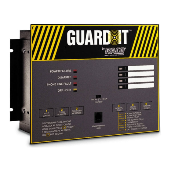
Page 16: Guard-It Tm Front Panel Diagram
Wiring Connections Guard-It Front Panel Diagram Channel Light Indications: Flashing red indicates loss of external 12 VDC power. After 5 minutes, alarm calls will be placed. Upon acknowledgement, Steady green - Normal light is on with no flashing until power is restored. -
Page 17: Tm Autodialer
Programming Your Guard-It Autodialer Programming Your Guard-It Autodialer Programming Menu To program your Guard-It autodialer, you will need a standard touch-tone telephone. Telephones which have the keypad located separately from the handset, are most convenient for this purpose. Just plug the telephone temporarily into the Programming Jack on the front panel of the product, lift the receiver, and follow the voice menu to enter your programming and record your voice messages. -
Page 18: Guard-It Tm Programming Flow Chart
Programming Your Guard-It Autodialer Programming Flow Chart Guard-It 4 - 2 Guard-It Owner's Manual... -
Page 19: Input Configuration
If you delay more than five seconds without pressing any new key, the Product will treat this the same as pressing the pound (#) key, except when recording messages. Also note that your Guard-It autodialer will not respond to new alarm conditions while you are programming. The LED’s will generally remain in the state they were in prior to the beginning of the programming session, until a few seconds after the programming session has ended. -
Page 20: Phone Number Programming
Refer to Appendix A for additional information on programming for analog signal inputs. 4.1.2 Phone Number Programming You must program at least one phone number for your Guard-It autodialer PHONE to dial when it has an alarm to report. NUMBERS... -
Page 21: Recording Voice Messages
[1] to review the existing set of five messages, or [2] to begin the sequence of recording all five messages. If you select [2] to begin the recording sequence, the Guard-It autodialer moves you automatically through the sequence of all five messages to record, starting with the message for input channel number one. -
Page 22: General Programming Items
Programming Your Guard-It Autodialer For any input channels which you have programmed for analog signal input, record the message in the form of: “The water level percentage is”. Whenever you call in or when an alarm call is placed, analog channels will be reported with the message you record followed immediately by the percentage value. -
Page 23: Answer Delay
Guard-It autodialer answers it. If the line is in use by an extension phone when the Guard-It tries to place an alarm call, the call will not be completed, but the messages will be heard on the extension phone. -
Page 24: Dialing Delay
10 minutes. 4.1.4.5 [5] Dialing Delay If you want your Guard-It autodialer to place alarm calls to a numerical pager, you will need to refer to Appendix E for special instructions, which include programming the special Dialing Delay. -
Page 25: Call Progress Control
Note: Note that if this feature is turned on and there is another phone device connected to the Guard-It autodialer’s phone line, if that device happens to be “off hook” (in use) when the product checks the phone line, a phone line fault indication may occur. -
Page 26: Status Report (Input Review)
REVIEW feature to write all your programming entries on the Programming Log Sheet provided in this manual. This will allow you to easily re-create your Guard-It autodialer setup should it ever be necessary to replace or reprogram the unit. It is also helpful in the event you need to call for Customer Support. -
Page 27: Restoring Programming To Factory Default Settings
Autodialer Restoring Programming To Factory Default Settings It is possible to restore your Guard-It autodialer to factory default settings for all programming items, including clearing out all recorded messages. To do this, locate the plugged hole in the top of the enclosure, and remove the plug. - Page 28 Programming Your Guard-It Autodialer PROGRAMMING LOG SHEET REPROGRAMMED PROGRAM ITEM DEFAULT RANGE Input Channel 1 Alarm on Closed Analog, Closed Open Analog Circuit Alarm Closed, __________% __________% Alarm Open, Off High Set Point Low Set Point Closed Open Input Channel 2...
- Page 29 Programming Your Guard-It Autodialer PROGRAM ITEM DEFAULT RANGE REPROGRAMMED TO: Ring Answer Delay 1 ring 1-20 Time Between Callls 2.0 seconds 0.1-999.9[1] Alarm Reset Time 1.0 hours 0.1-99.9 Tone/Pulse Dialing Auto detect Tone, Pulse, Auto Pager Dialing Delay 10.0 seconds 0.1-99.9...
-
Page 30: The Guard-It
The Guard-It Autodialer In Operation The Alarm Process Much of the operation of the Guard-it was explained in the previous chapter on programming. To review the sequence of events that starts with the detection of a fault condition on a given input channel, refer to the Alarm Process diagram. -
Page 31: Guard-It Tm Alarm Process Diagram
The Guard-It Autodialer In Operation Guard-It Alarm Process Diagram Guard It Alarm Process Diagram NORMAL Return to Normal No fault detected. if fault is cleared. ACKNOWLEDGED FAULT DETECTED ALARM Waiting for Alarm Waiting for Alarm Trip Delay Reset Time to elapse. Meanwhile, to elapse. -
Page 32: Receiving And Acknowledging An Alarm Call
Receiving And Acknowledging An Alarm Call When you receive an alarm call from your Guard-it autodialer, listen to the message to learn what alarm(s) exist. The message round will start with the Station ID message, followed by the specific alarm message for the input channel(s) in alarm, and/or a message stating “power is off”. -
Page 33: Power Failure Alarms
You may also acknowledge the alarm by placing a return call to the Guard-it autodialer. The best way to do this is to wait for the alarm call to end before you place your return call, so that the line will not be busy. -
Page 34: Acknowledging An Alarm From The Front Panel
The Guard-It Autodialer In Operation Acknowledging An Alarm From The Front Panel To acknowledge an alarm from the front panel, move the selector switch to the DISARMED position, then return it to the READY position. The product must not be in programming mode or presently placing a phone call, for the alarm to be acknowledged in this way. - Page 35 The Guard-It Autodialer In Operation Guard-It Owner's Manual...
-
Page 36: Troubleshooting & Repair Service
Most other apparent problems, especially at startup, are the result of incorrect connection or programming, or misunderstanding of how the product operates. If after reviewing this manual you still have difficulty, Raco’s Customer Support department is available from 8:00 a.m. through 4:30 p.m. P.S.T. on weekdays. -
Page 37: Returning Parts To Factory
Troubleshooting Returning Parts to Factory Pack all parts well! Send the unit to the address below: RACO Manufacturing and Engineering Co. 1400 62nd Street Emeryville, CA 94608 Remember to: Put return address on package. Include a packing slip. Have serial # and RMA # handy when you call in for tracking. -
Page 38: Testing
You might temporarily program an alarm reset time of, say, four hours, so that you would get a new set of calls every four hours until the battery lost charge. Guard-It Owner's Manual... - Page 39 Testing Guard-It Owner's Manual...
-
Page 40: Maintenance
Replacements for this battery must be ordered near the time of changeout, since long storage on a shelf without a charger will damage the battery. It may be ordered from Raco or from the manufacturer as printed on the battery. Guard-It... - Page 41 Maintenance Guard-It Owner's Manual...
-
Page 42: Analog (4-20 Ma) Inputs
The easiest way to verify that there are no grounding problems, is to verify that the current in the loop does not change when the Guard-It autodialer is added to the loop. For example, if there is a chart recorder or readout device in the current loop,... -
Page 43: Programming For Analog Signal Inputs
Appendix A If you are troubleshooting by making voltage measurements across the signal input connection points on the Guard-It autodialer, bear in mind that if the product is turned off or if it has not been programmed for analog input, an internal voltage clamp will result in a fixed voltage drop of about 7 VDC. - Page 44 To turn off a given alarm set point so that it will not create an alarm, press “star” (*) and then pound (#). In operation, whenever a high or low level alarm setpoint is exceeded continuously for the duration of the programmed alarm trip delay, an unacknowledged alarm will occur. Guard-It Owner's Manual...
-
Page 45: Analog Translation Table
6.4 Millamperes 7.2 Millamperes 8.0 Millamperes 8.8 Millamperes 9.6 Millamperes 10.4 Millamperes 11.2 Millamperes 12.0 Millamperes 12.8 Millamperes 13.6 Millamperes 14.4 Millamperes 15.2 Millamperes 16.0 Millamperes 16.8 Millamperes 17.6 Millamperes 18.4 Millamperes 19.2 Millamperes 20.0 Millamperes 100% Guard-It Owner's Manual... -
Page 46: Analog 4-20 Ma Signal Input Wiring Connection Diagram
Appendix A Analog 4-20 ma Signal Input Wiring Connection Diagram Guard-It Owner's Manual... - Page 47 Appendix A Guard-It Owner's Manual...
-
Page 48: Connecting Digital Logic Signal Inputs
Guard-It autodialer is the same as for the 5 volt logic system. A logic “0” will be interpreted by the Guard-It autodialer as a closed circuit, and a logic “1” will be interpreted as an open circuit. -
Page 49: Digital Logic Signal Input Wiring Connection Diagram
Connecting Digital Logic Signal Inputs Digital Logic Signal Input Wiring Connection Diagram Guard-It Owner's Manual... -
Page 50: Digital Alarm Output (Dao)
VDC logic input such as found on PLC’s, but due to the resistor connected to +5VDC, an external pullup resistor (nominally 1K) to a +24 VDC source may be needed. Optional Digital Alarm Output (DAO) Connection Diagram Removable Connector Block 1 C 2 Device to be activated 12 V DC Power Guard-It Owner's Manual... - Page 51 Digital Alarm Output (DAO) Guard-It Owner's Manual...
-
Page 52: Optional External Gel Cell Backup Battery
6 hours depending on the number of alarm calls placed and other factors. Optional External Battery Connection Diagram Removable Connector Block 1 C 2 6 Volt Gel Cell Lead Acid Battery 12 V DC Power Guard-It Owner's Manual... - Page 53 Optional External Gel Cell Backup Battery Guard-It Owner's Manual...
-
Page 54: Programming For Use With Numeric
To call and cause a display on a numeric pager, your Guard-It autodialer will do essentially the same thing, except that it will wait for a delay period which you set, instead of listening for the pager system’s beep, before sending the... - Page 55 With the extended phone number and Dialing Delay value fully programmed, it is best to verify (three times is suggested) that the Guard-It autodialer will successfully cause the pager to be reached with the intended display.
-
Page 56: Enclosure Mechanicals & Wiring Diagrams
Enclosure Mechanicals & Wiring Diagrams ENCLOSURE MECHANICALS & WIRING DIAGRAMS Mounting the Guard-It Autodialer Enclosure Flush into a Front Panel Mounting Screws (6-32) Cutout Front Panel (maximum thickness 1/8") You will need a rectangular cutout in the panel to clear 6-3/16"... -
Page 57: Mounting The Guard-It
Enclosure Mechanicals & Wiring Diagrams Mounting the Guard-It Autodialer Enclosure onto a Back Surface GUARD IT Front Panel not shown in diagrams. Mounting Brackets Mounting Screws (6-32) 9.0" Mounting Center 3.6" 6.1" Mounting Center 8.0" F - 2 Guard-It Owner's... - Page 58 Enclosure Mechanicals & Wiring Diagrams Guard-It Owner's Manual F - 3...
-
Page 59: Guard-It /Cellularm Wiring Diagram
Enclosure Mechanicals & Wiring Diagrams Guard-It Cellularm Wiring Diagram E n c l o s u r e D o o r D e a d F r o n t P a n e l C e l l P h o n e... -
Page 60: Guard-It
Company or an authorized agent. It is the responsibility of users requiring service to report the need for service to our Company or to one of our authorized agents. Service can be obtained at Raco Manufacturing & Engineering Company, 1400 62nd Street, Emeryville, California, 94608;... - Page 61 Guard It Owner's Manual...
Need help?
Do you have a question about the Guard-It and is the answer not in the manual?
Questions and answers