
Related Manuals for SILENT KNIGHT SK-5208

Summary of Contents for SILENT KNIGHT SK-5208
- Page 1 MODEL SK-5208 Fire Control/ Communicator Installation and Operations Manual Part Number 151204 Rev L...
-
Page 3: Installation Procedure
Do not tighten screw terminals more than 9 in-lbs. Over-tightening may damage threads, resulting in reduced terminal contact pressure and difficulty with screw terminal removal. Silent Knight fire alarm control panels contain static-sensitive components. Always ground yourself with a proper wrist strap before handling any circuits so that static charges are removed from the body. - Page 4 VIP-Series Voice Integration Package Installation/Operation Manual FACP operation and reliability depend upon proper installation. While installing a fire alarm system may make lower insurance rates possible, it is not a substitute for fire insurance! An automatic fire alarm system - typically made up of smoke detectors, heat detectors, manual pull stations, audible warning devices, and a fire alarm control with remote notification capability - can provide early warning of a developing fire.
-
Page 5: Table Of Contents
Contents Contents Section 1 Introduction .............................. 1-1 Model SK-5208 Features ......................... 1-1 About This Manual ..........................1-2 1.2.1 Optional Accessories ........................1-2 Limitations of Fire Alarm Systems ..................1-3 Section 2 Agency Listings and Requirements ................ 2-1 Federal Communications Commission (FCC) ..................2-1 Underwriters Laboratories (UL) ...................... - Page 6 3.14.2.2 Wiring the SK-5235 ......................3-22 3.14.3 Model SK-5280 Status Display Module ..................3-23 3.14.3.1 Mounting the SK-5280 ......................3-25 Mounting the SK-5280 into SK-5208 Cabinet ..............3-25 Mounting the SK-5280 into the SK-2190 Accessory Cabinet..........3-26 3.14.3.2 Wiring Relays ........................3-27 3.14.3.3 Wiring LEDs to Outputs ......................
- Page 7 Earth Fault Resistance ..........................7-4 Appendix A Compatible Devices ........................A-1 Notification Appliances .......................... A-1 Two-Wire Smoke Detectors ........................A-11 Four Wire Smoke Detectors ........................A-13 Silent Knight Fire Product Warranty and Return Policy SK-5208 Plus Basic Operating Instructions P/N 151214 Rev. A...
- Page 8 Installation Manual...
-
Page 9: Introduction
Section 1 Introduction The Model SK-5208 is an 24-volt 10-zone fire alarm control panel (expandable up to 30 zones using SK-5217 Zone Expanders) with a digital communicator that meets NFPA 72 requirements. The SK-5208 cabinet can be surface mounted or semi-flush mounted. -
Page 10: About This Manual
Model What It Does SK-5217 Zone Expander Adds 10 zones to the SK-5208 for a total expansion of the system to 30 zones. SK-2190 Accessory Cabinet Used for remote mounting of the SK-5217 Zone Expander. Dimensions: 10-3/8”W x 10-3/16”H x 3”D (26.35 cm W x 25.88 cm H x 7.62 cm D) -
Page 11: Limitations Of Fire Alarm Systems
Introduction Limitations of Fire Alarm Systems Manufacturer recommends that smoke and/or heat detectors be located throughout a protected premise following the recommendations of the current edition of the National Fire Protection Association Standard 72 (NFPA 72), manufacturer’s recommendations, State and local codes, and the recommendations contained in Guide for the Proper Use of System Smoke Detectors, which is made available at no charge to all installing dealers. - Page 12 Model SK-5208 Fire Control/Communicator Installation and Operation Manual In general, fire alarm systems and devices will not work without power and will not function properly unless they are maintained and tested regularly. While installing a fire alarm system may make the owner eligible for a lower insurance rate, an alarm system is not a substitute for insurance.
-
Page 13: Agency Listings And Requirements
203-484-7161 800-328-0103 6. If the SK-5208 causes harm to the telephone network, the telephone company will notify the user in advance that temporary discontinuance of service may be required. When advance notice is not practical, the telephone company will notify the user as soon as possible. -
Page 14: Underwriters Laboratories (Ul)
Local Protected Fire Alarm Systems, Auxiliary Protected Fire Alarm Systems for Fire Alarm Service (City Box), Remote Station Protected Fire Alarm Systems and water releasing service. If the SK-5208 and its accessories are to be used as part of a UL installation, carefully read the UL requirements in this section. -
Page 15: Control Panel Installation
Notification Power 3A max. per output (6A total) Environmental Specifications It is important to protect the SK-5208 control panel from water. To prevent water damage, the following conditions should be AVOIDED when mounting the units: • Do not mount directly on exterior walls, especially masonry walls (condensation). -
Page 16: Wiring Specifications
Model SK-5208 Fire Control/Communicator Installation and Operation Manual Wiring Specifications To avoid induced noise (transfer of electrical energy from one wire to another), keep input wiring isolated from high current output and power wiring. Induced noise can interfere with telephone communication or even cause false alarms. Avoid pulling one multiconductor cable for the entire panel. -
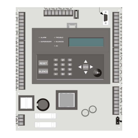
Page 17: Control Board Components
Annunciator Figure 3-1 Wire Routing Example Control Board Components Figure 3-2 is a wiring diagram for wiring the Model SK-5208 panel. Figure 3-2 Model SK-5208 Board Layout Refer to Section 3.9 for complete description of control panel terminal connections. P/N 151204... - Page 18 Model SK-5208 Fire Control/Communicator Installation and Operation Manual Phone Line 1 Phone Line 2 RS232 Connections Connections Programming Connector Class A Class B Programmable Zone Output Relays Inputs Class B Zone Inputs Circuit Remote Annunciator Connections SBUS Connections Input Backup...
-
Page 19: Mounting The Sk-5208
16" W x 26.4" H x 4" D (40.64 cm W x 67.06 cm H x 10.16 cm D). The SK-5208 panel should be located within a secured area, where it is accessible to main drop wiring runs and where it can be easily tested and serviced. End-users responsible for maintaining the panel should be able to hear alarms and troubles. -
Page 20: Current Draw Calculations
Filling in the Current Draw Worksheet, Table 3-2 (Section 3.6.2) 1. For the SK-5208, the worst case current draw is listed for the panel and panel accessories. Fill in the number of devices that will be used in the system and compute the current draw requirements for alarm and standby. - Page 21 Use next size battery with capacity greater than required. The SK-5208 and SK-5217 limits alarm current to 95mA per zone. The SK-5208 alarm current includes 10% of zones in alarm, but in no case less then three zones per UL864...
-
Page 22: Maximum Battery Standby Load
Warning! Silent Knight does not support the use of batteries smaller than those listed in Table 3-3. If you use a battery too small for the installation, the system could overload the battery resulting in the installation having less than the required 24 hours standby power. -
Page 23: Ac Wiring
To reduce the risk of electrical shock, make sure that all power has been turned off or disconnected before attempting to connect the Model SK-5208 control panel. Do NOT apply power to this panel until all accessories are properly connected. -
Page 24: Backup Batteries
Model SK-5208 Fire Control/Communicator Installation and Operation Manual Backup Batteries The control panel battery charge capacity is 7.0 to 35.0 AH. Use 12V batteries of the same AH rating. Determine the correct AH rating as per your current load calculation (see 3.6.2). -
Page 25: Terminal Strip Description
Control Panel Installation Terminal Strip Description The terminal strips on the PC board are non-removable. Table 3-4 lists the functions of each terminal. See Section 3.4 for the board layout. Table 3-4: Terminal Descriptions Terminal Function Terminal Label Comments Number Zone 1 input Class A (Style D) or Class B (Style B). - Page 26 Model SK-5208 Fire Control/Communicator Installation and Operation Manual Table 3-4: Terminal Descriptions Terminal Function Terminal Label Comments Number 3 Amp maximum per circuit. Voltage 27.4 VDC, 1.5 Notification Appliance NAC4 Ohms Maximum. Circuit 4 Note: Total control panel current is 6 Amps.
-
Page 27: Telephone Line Connection
A situation could occur where both phone lines appear to be good, but the dialer cannot get through to the central station on the first line. In this case, the SK-5208 will switch phone lines and attempt the call again using the second line. Make sure the phone lines are programmed properly (see Section 4). -
Page 28: Detector Installation
When a single open or ground fault occurs, the audible trouble signal will sound and the SK-5208 will report the trouble to the central station or remote station (if programmed to report troubles). If reporting to a remote station troubles may be transmitted to a secondary location. -
Page 29: Class B (Style B) Zones
The detection of an open will cause the audible trouble signal to sound and the SK-5208 will report the trouble to the central or remote station (if programmed to do so). -
Page 30: Four-Wire Smoke Detector Connection
Note: Mount the PAM-2 and the end-of-line resistor at the last device on the circuit. Supervised Power Limited Figure 3-7 Four-Wire Smoke Detector Wiring See Appendix A for a list of four-wire smoke detectors that may be used with the SK-5208. 3-16 P/N 151204... -
Page 31: Two-Wire Smoke Detector Connection
Model 7628 Figure 3-8 Two-Wire Smoke Detector Wiring See Appendix A for a list of two-wire smoke detectors that may be used with the SK-5208. Note: Two-wire detectors can be configured for Enhanced Mode. Enhanced mode is smoke verification for zones with 2-wire detectors and contact type devices, such as pull stations, used on the same circuit. -
Page 32: Supervised Notification Appliance Outputs
3 Amp maximum current draw from any single NAC output (not to exceed a total current draw of 6 amps for the control panel). See Appendix A for a list of the UL notification appliances that can be used with the SK-5208. Contact Silent Knight if you have any questions about compatible notification circuits. -
Page 33: Auxiliary Relays
(loss of AC, low battery, failed to communicate, phone line troubles, fire drills, and notification circuit troubles). Refer to the SK-5208 programming manual for more information. Figure 3-10 shows the relay contact connections using a door holder application as an example. -
Page 34: Accessory Devices
Model SK-5208 Fire Control/Communicator Installation and Operation Manual 3.14 Accessory Devices The section describes how to install the SK-5235 Remote Annunciator, SK-5217 Zone Expander, the 5824 Serial/Parallel Printer Module, and the SK-5280 Status Display Module. All circuits are 24 VDC regulated. -
Page 35: Model Sk-5235 Remote Annunciator
Control Panel Installation 3.14.2 Model SK-5235 Remote Annunciator The SK-5235 performs all system operation. It also provides trouble and alarm information and can be used for programming. The control panel can support up to six SK-5235 Remote Annunciators. Upon initial power up, the address of each SK-5235 is displayed on the LCD. (Annunciators with address 0 will not be supervised.) 3.14.2.1 Mounting the SK-5235 Remote Annunciator The SK-5235 Remote Annunciators must be mounted on a dual gang electrical box. -
Page 36: Wiring The Sk-5235
Model SK-5208 Fire Control/Communicator Installation and Operation Manual 3.14.2.2 Wiring the SK-5235 Follow these steps to properly wire the SK-5235 to the control panel. 1. Remove power from the control panel. 2. Wire the SK-5235s as shown in Figure 3-12. -
Page 37: Model Sk-5280 Status Display Module
Control Panel Installation 3.14.3 Model SK-5280 Status Display Module The Model SK-5280 Status Display module provides outputs and control functions for remote annunciation of alarm, trouble, and supervisories for each zone.The system can supervise up to eight SK-5280 Status Display Modules. Note: The driver outputs are non-supervised. - Page 38 Model SK-5208 Fire Control/Communicator Installation and Operation Manual The SK-5280 can be used to interface to LED annunciator. The SK-5280 can be programmed to indicate alarms and trouble status for; zones 1 - 10, zones 11 - 20, zones 21 - 30, or system status outputs. See Section 4.2.11.
-
Page 39: Mounting The Sk-5280
Control Panel Installation 3.14.3.1 Mounting the SK-5280 The SK-5280 into a metal bracket and standoffs in the SK-5208 cabinet or into SK-2190 accessory cabinet. Mounting the SK-5280 into SK-5208 Cabinet Follow these steps to properly mount the SK-5280 into the SK-5208 cabinet: 1. -
Page 40: Mounting The Sk-5280 Into The Sk-2190 Accessory Cabinet
Holes Figure 3-16 Model SK-5280 Remote Installation 4. Connect the SK-5280 to the SK-5208 control panel as shown in Figure 3-14. 5. Set the ID number (see Figure 3-13 for ID DIP switch location). See also Section 3.14.1for information on setting ID numbers. -
Page 41: Wiring Relays
Control Panel Installation 3.14.3.2 Wiring Relays The four on-board relays can be triggered by the active low outputs. For example, the alarm outputs can all be wired to relay 3 and the trouble outputs can be wired to relay 4 (see Figure 3-17). -
Page 42: Model Sk-5217 Zone Expander Installation
Model SK-5208 Fire Control/Communicator Installation and Operation Manual 3.14.4 Model SK-5217 Zone Expander Installation The Model SK-5217 provides the SK-5208 with ten additional Class B (style B) zones. The SK-5217 connects to the SK-5208 control panel via the SBUS as shown in Figure 3-19. -
Page 43: Zone Inputs
Control Panel Installation 3.14.4.1 Zone Inputs Figure 3-20 and Figure 3-21 shows how to wire detectors to the SK-5217. Use a 4.7k end of line resistor for each Class B circuit. The EOL must be wired in parallel with the normally open contact farthest from the panel. -
Page 44: Mounting Instructions
Model SK-5208 Fire Control/Communicator Installation and Operation Manual 3.14.4.2 Mounting Instructions The SK-5217 into a metal bracket and standoffs in the SK-5208 cabinet or into SK-2190 accessory cabinet. Mounting the SK-5217 into SK-5208 Cabinet Follow these steps to properly mount the SK-5217 zone expander into the SK-5208 cabinet: 1. -
Page 45: Mounting The Sk-5217 Into The Sk-2190 Accessory Cabinet
Holes Figure 3-23 Model SK-5217 Remote Installation 4. Connect the SK-5217 to the SK-5208 control panel as shown in Figure 3-19. 5. Set the ID code (see Section 3.14.1). If ID code 1 is selected the SK-5217 will input zones 11 - 20. -
Page 46: Model 5824 Installation Instructions
Model SK-5208 Fire Control/Communicator Installation and Operation Manual 3.14.5 Model 5824 Installation Instructions The Model 5824 provides the 5208 with the ability to communicate to a serial or parallel printer to print the event log. You can use one 5824 on the 5208. The 5824 is for ancillary use only. -
Page 47: 5824 Sbus Connections
Control Panel Installation 3.14.5.2 5824 SBUS Connections Figure 3-24 illustrates how the 5824 connects to the 5208 control panel. Control Panel Supervised Power Limited 5824 Figure 3-24 5824 Connections Serial Port 5824 Parallel Port ID Selector Switches Figure 3-25 Model 5824 Serial/Parallel Port, and ID Selector Switch location P/N 151204 3-33... -
Page 48: Special Applications
3. Program NAC #4 to be direct connect from the NAC Options menu. Relay #4 will automatically be configured to indicate system troubles. Note: It is not possible to reset the remote indication until you clear the condition and reset the SK-5208. 5220... -
Page 49: Nfpa 72 Polarity Reversal
To install the 5220 for polarity reversal, follow the steps below: 1. Locate the knockout on the right side of the SK-5208 cabinet to connect the 5220 using a short piece of conduit (must not exceed 20 feet in length). -
Page 50: Keltron 95M3158 Tones Transmitter Module
Note: The 3158 Keltron Module must be mounted within 3 feet of the control panel and all wiring must be run in conduit. The Keltron Module shall be enclosed in the TBX1 enclosure. 1. Wire the 3158 to the SK-5208 as shown in the Figure 3-28. 2. Program NAC 4 for Direct Connect (see Section 4.2.4). -
Page 51: Using A Mr-201/T Control Relay From Air Products
Control Panel Installation 3.15.3 Using a MR-201/T Control Relay From Air Products When the MR-201/T control relay is wired for polarity reversal, it reports alarm and trouble events to a remote site. Alarms will override trouble conditions and it will not be possible to reset the remote indicator until the condition is cleared and the control panel is reset. - Page 52 Model SK-5208 Fire Control/Communicator Installation and Operation Manual 3-38 P/N 151204...
-
Page 53: Programming
Section 4 Programming The SK-5208 control panel can be programmed from either the on-board annunciator or the SK-5235 remote annunciator. You must be in Programming Mode to program the control panel. Keypad Operation During Programming This section describes the function of the buttons on the keypad while in program mode. -
Page 54: Special Characters
Model SK-5208 Fire Control/Communicator Installation and Operation Manual 4.1.1 Special Characters Special characters are characters used while dialing such as pause, *, #, or 2nd dial tone. Table 4-1 list the Special characters and what they mean. Table 4-1: Special Characters... -
Page 55: Programming Flow
Programming Programming Flow Figure 4-2 provides an overview of the programming menu flow. Figure 4-3 through Figure 4- 13 illustrate the programming flow within each option. The arrows indicate how to maneuver through programming. Figure 4-2 Programming Overview Flow Chart P/N 151204... -
Page 56: Zone Options
Model SK-5208 Fire Control/Communicator Installation and Operation Manual 4.2.1 Zone Options Figure 4-3 illustrates, in more detail, the programming flow when in the zone options menu. Figure 4-3 Zone Options P/N 151204... -
Page 57: Misc System Option
Programming 4.2.2 Misc System Option Figure 4-4 illustrates, in more detail, the programming flow when in the misc system menu. Figure 4-4 Miscellaneous System Options P/N 151204... -
Page 58: Nac Cadence
Model SK-5208 Fire Control/Communicator Installation and Operation Manual 4.2.3 NAC Cadence Figure 4-5 illustrates, in more detail, the programming flow when in the NAC cadence menu. Figure 4-5 NAC Cadence 4.2.3.1 Cadence Patterns The cadence patterns shown in Table 4-2 can be selected for NAC outputs. Each NAC can select an output pattern. -
Page 59: Nac Options
Programming 4.2.4 NAC Options Figure 4-6 illustrates, in more detail, the programming flow when in the NAC options menu. Figure 4-6 NAC Options Programming Menu P/N 151204... -
Page 60: Relay Options
Model SK-5208 Fire Control/Communicator Installation and Operation Manual 4.2.5 Relay Options Figure 4-7 illustrates, in more detail, the programming flow when in the relay options menu. Figure 4-7 Relay Options Programming Menu P/N 151204... -
Page 61: User Code
Programming 4.2.6 User Code Figure 4-8 illustrates, in more detail, the programming flow when in the user code menu. Figure 4-8 User Code Programming Menu P/N 151204... -
Page 62: Account
Model SK-5208 Fire Control/Communicator Installation and Operation Manual 4.2.7 Account Figure 4-9 illustrates, in more detail, the programming flow when in the account menu. Figure 4-9 Account Programming Menu Must The dialer MUST report events in this family to this account. -
Page 63: Computer Options
Programming 4.2.8 Computer Options Figure 4-10 illustrates, in more detail, the programming flow when in the computer options menu. Figure 4-10 Computer Options Programming Menu Note: Computer CIC & Phone can also use special characters as described in Section 4.1.1. 4.2.8.1 Computer Code In order to remote download to a control, the computer code programmed in the panel, and the computer code used in the downloading software must match. -
Page 64: Line Options
Model SK-5208 Fire Control/Communicator Installation and Operation Manual 4.2.9 Line Options Figure 4-11 illustrates, in more detail, the programming flow when in the line options menu. Figure 4-11 Line Options Programming Menu Note: Line prefix can also use special characters as described in Section 4.1.1. -
Page 65: Misc Reporting
Programming 4.2.10 Misc Reporting Figure 4-12 illustrates, in more detail, the programming flow when in the miscellaneous reporting menu. Figure 4-12 Misc Reporting Programming Menu P/N 151204 4-13... -
Page 66: 5280 Outputs
Model SK-5208 Fire Control/Communicator Installation and Operation Manual 4.2.11 5280 Outputs Figure 4-13 illustrates, in more detail, the programming flow when in the SK-5280 outputs menu. Figure 4-13 5280 Outputs Programming Menu If Zones 1-10 is selected then the SK-5280 will output when alarms and troubles occur for zones 1 through 10. -
Page 67: 5824 Expander Options
Programming 4.2.12 5824 Expander Options Figure 4-14 illustrates, in more detail, the programming flow for the 5824 serial/parallel module. Figure 4-14 5824 Programming Options Flow Chart P/N 151204 4-15... -
Page 68: Dst/Clk Options
Model SK-5208 Fire Control/Communicator Installation and Operation Manual 4.2.13 DST/Clk Options Figure 4-15 illustrates the programming flow for the Daylight Saving Time (DST) and clock source options. Figure 4-15 DST/Clk Options Flow Chart 4-16 P/N 151204... -
Page 69: Programming Options
Programming Programming Options Table 4-4 list all the programming options and the items that can be modified within those programming option menus. Note: Programming options that have a # in the Programming Options column have multiple programmable components. See Section 4.1.2 for additional information. Table 4-4: Programming Options Programming Menu Item... - Page 70 Model SK-5208 Fire Control/Communicator Installation and Operation Manual Table 4-4: Programming Options Programming Menu Item Choices Default Comments Option Note: Alarm verification feature must not be None used if the FACP is being used for releasing. Smoke verification for zones with 2- or 4-wire Smoke detectors.
- Page 71 Programming Table 4-4: Programming Options Programming Menu Item Choices Default Comments Option If Yes is selected you are not required to enter a Code for operator level functions, such as Reset, Misc System Plex Door Silence, and Display Event History. (cont.) Note: If this option is enabled, the PLEX-2 accessory must be installed on the control panel.
- Page 72 Model SK-5208 Fire Control/Communicator Installation and Operation Manual Table 4-4: Programming Options Programming Menu Item Choices Default Comments Option If a relay is selected, that relay can be silenced for No Relays Silence Relay _ _ _ _ Trouble and Supervisory conditions only. (This selected includes relays programmed for AC Trbl.)
- Page 73 Programming Table 4-4: Programming Options Programming Menu Item Choices Default Comments Option 1: 105208 Enter any value from 000001 to 999999. Account Enter a 6-digits 2: 205208 numbers with less than 6 digits must use leading Account <#> # number 3: 305208 zeros.
- Page 74 Model SK-5208 Fire Control/Communicator Installation and Operation Manual Table 4-4: Programming Options Programming Menu Item Choices Default Comments Option Not Used This disables the phone line. Attempts 1 through 6 will be DTMF, then the dialer will alternate between Rotary and DTMF for...
- Page 75 Programming Table 4-4: Programming Options Programming Menu Item Choices Default Comments Option Not Used Zones 1_10 5280 (1 - 8) # 5280 # Zones 11_20 Outputs Zones 21_30 System Sets the serial bus address for the 5824. Use a 0 to 5824 ID 0 - 7 disable this feature.
- Page 76 Model SK-5208 Fire Control/Communicator Installation and Operation Manual Table 4-4: Programming Options Programming Menu Item Choices Default Comments Option The panel’s AC line frequency is selectable for 60, 60 Hz 50 Hz, or Internal. AC Frequency feature dictates how the control panel will calculate time based on the AC line frequency used in the installation site.
-
Page 77: Operation
Section 5 Operation To operate the SK-5208 you can use either the on-board touchpad or the Model SK-5235 Remote Annunciator. Figure 5-1 Model SK-5235 Remote Annunciator Important! Upon initial power up there is a 45 second delay before the initiation circuits become active. -
Page 78: On-Board Touchpad And Sk-5235 Operation
Model SK-5208 Fire Control/Communicator Installation and Operation Manual On-board Touchpad and SK-5235 Operation Basic operations for the on-board annunciator (touchpad) and SK-5235 are described in Table 5-1. If you are using an annunciator key or the Flex Door option, you are not required to enter a code for operator level functions. -
Page 79: View Control Panel Firmware Number And Revision
Operation 5.2.1 View Control Panel Firmware Number and Revision When and the code is entered The system will perform a display lamp test and a communication test. Also displays Firmware number and revision as shown in Figure 5-3. Control Firmware Revision Letter Number Dialer Firmware... -
Page 80: Led Indicators
Model SK-5208 Fire Control/Communicator Installation and Operation Manual LED Indicators Five light emitting diodes (LEDs) appear in the SK-5208 built in annunciator and remote annunciator. The chart below explains the meaning of these LEDs. Table 5-2 Status Condition Normal condition ALARM (red) System in alarm and all alarms have been acknowledged. -
Page 81: Releasing Operation
Operation Releasing Operation This system can perform two types of releasing operation, cross alarm releasing, and double interlock releasing operations. Install in accordance with NFPA 72 paragraphs 3-8.3.2.3.3 and 3-8.3.2.3.3.2. 5.5.1 Cross Alarm Operation The fire alarm control panel has two cross alert groups to select from, Cross Alert A and Cross Alert B that accommodate releasing water systems. - Page 82 Model SK-5208 Fire Control/Communicator Installation and Operation Manual A Model 7641 EOL resistor/diode assembly is required when connecting the FACP to releasing solenoids. The 7641 allows the FACP to supervise the wiring between its NACs and the releasing solenoid. Table 5-4: Approved Releasing Solenoids...
-
Page 83: Double Interlock Releasing Operation
Operation 5.5.2 Double Interlock Releasing Operation A typical double interlock releasing system would be programmed with a minimum of two zones selected for “Cross Alert A”, one zone selected as “Man. Release A”, and one selected as “Interlock A”. Additional zones can be selected as Cross Alert or Manual Release. This double interlock system requires both cross alert and manual release verification zones. -
Page 84: Smoke Alarm Verification
Model SK-5208 Fire Control/Communicator Installation and Operation Manual Smoke Alarm Verification Figure 5-6 illustrates how the Smoke Alarm Verification cycle operates. Figure 5-6 Smoke Verification Cycle During the Confirmation Period if there is no alarm indication then the system will return to normal operation. -
Page 85: System Testing
Yes or No Mapped NACs: The LCD will indicate that you are in walk test mode. When a zone is tripped, the SK-5208 will activate the bell outputs for approximately six second and will cycle smoke power off and on for the programmed time interval. When smoke power is restored, there is a two-second power up delay before the zone will respond to additional test inputs. -
Page 86: Communicating With A Programming Computer
An installer at the panel site can initiate communications between the panel and a computer running the Silent Knight Software Suite SKSS. In order for this communication to function properly both the computer (running the software) and the control panel must have matching computer account numbers and computer access codes. -
Page 87: Having Remote Computer Call The Control Panel
Operation 5.8.1.2 Having Remote Computer Call the Control Panel If the computer initiates the call then answering machine bypass (see Section 4.2.8) may need to be selected. To initiate communication: 1. From the SKSS Up/Downloading software File Menu, select the download or upload menu item you want to schedule. -
Page 88: Directly Connecting To A Programming Computer
Model SK-5208 Fire Control/Communicator Installation and Operation Manual 5.8.2 Directly Connecting to a Programming Computer The control panel can be up or downloaded from a computer that is directly connected to the control panel. Note: This connection is to be used as a temporary connection and should be disconnected after programming is completed. -
Page 89: Reporting
The SK-5208 can transmit information in four different formats. This section describes the four basic reporting formats of the SK-5208 and the codes that they send to a central station receiver. Of these four formats some of the formats offer a more specific selection for that format. -
Page 90: Reporting Codes
Model SK-5208 Fire Control/Communicator Installation and Operation Manual Reporting Codes Table 6-2 list the events sent by the SK-5208 and the code that is sent for that event by the type of reporting format used. Note: Codes under in the SK4/2 and 3/1 1400 & 2300 column are the codes programmed for 3/1 reporting formats in Misc Reporting. - Page 91 Reporting Table 6-2: Event and Reporting Code by Format Event SIA8 & 20 SK4/2 3/1 1400 &2300 Contact ID Fire Trouble/Clean-Me Trouble 1-30 FT1 - FT30 T1 - T0 Trouble Code 1 373 001 - 1 373 030 Fire Unbypass FU1-FU30 R1 - R9 Restore Code...
-
Page 92: Default Settings For 3/1 Format
Model SK-5208 Fire Control/Communicator Installation and Operation Manual Table 6-2: Event and Reporting Code by Format Event SIA8 & 20 SK4/2 3/1 1400 &2300 Contact ID Water Alarm Restore 1-30 WH1-WH30 AR1 - AR0 Alarm Restore Code 3 154 001 - 3 154 030... -
Page 93: Troubleshooting
Table 7-1: Error Messages Error Message Description Solution On power up the SK-5208 will check the flash for If an “option record” is not found FLASH Defaulted an “option record”. during power up, one will be created and the display will indicate “Flash Defaulted”... - Page 94 Model SK-5208 Fire Control/Communicator Installation and Operation Manual Table 7-1: Error Messages Error Message Description Solution Smoke power terminals 11, 14, 17, and 20 are This may occur when the maximum Smk Pwr Trb supervised. If the voltage between circuit ground...
-
Page 95: Earth Ground Fault Troubleshooting
Troubleshooting Earth Ground Fault Troubleshooting An Earth Fault Trb indicates that the panel has detected a short between any terminal on the panel and earth ground. To determine the location of the short, place a DC volt meter with ground on terminal 22 (circuit ground) and positive on any of the screws that secure the circuit board to the cabinet (earth ground). -
Page 96: Earth Fault Resistance
Model SK-5208 Fire Control/Communicator Installation and Operation Manual Earth Fault Resistance Table 7-2 list the earth fault resistance values for each applicable terminal on the FACP. Table 7-2: Earth Fault Resistance Values by Terminal Terminal Earth Fault Resistance Function Terminal Label... -
Page 97: Appendix A Compatible Devices
Appendix A Compatible Devices This section of the manual lists devices (smoke detectors and notification appliances) that are compatible with the SK-5208. Contact Silent Knight if you have a question about whether a device not listed here is compatible. Notification Appliances For proper operation, you must use polarized devices with a Model 7628 4.7k ohm EOL... - Page 98 Model SK-5208 Fire Control/Communicator Installation and Operation Manual Manufacturer Model Audio Visual Type Vibrating Bell Vibrating Bell Single Stroke Bell 2700 -M. -R, -T, -Y, -Z Strobe 2701 Series Strobe 2705 Series Strobe 2820 Snyc Temporal Horn/Strobe 2821 Snyc Temporal Horn/Strobe...
- Page 99 Compatible Devices Manufacturer Model Audio Visual Type Faraday 6223 Horn 6226 Horn/Strobe 6227 Horn/Strobe 6228 Horn/Strobe 6243 Electron-Mechanical Horn 6244 Electron-Mechanical Horn 6245 Electron-Mechanical Horn 6246 Electron-Mechanical Horn/Strobe 6247 Electron-Mechanical Horn/Strobe 6248 Electron-Mechanical Horn/Strobe 6300 Mini-Horn 6301 Mini-Horn 6302 Mini-Horn 6310 Mini-Horn/Strobe 6311...
- Page 100 Model SK-5208 Fire Control/Communicator Installation and Operation Manual Manufacturer Model Audio Visual Type P2415-FC Horn/Strobe P2415W-FC Horn/Strobe P2415K-FC Horn/Strobe P241575-FC Horn/Strobe P241575W-FC Horn/Strobe P241575F-FC Horn/Strobe P241575K-FC Horn/Strobe P2430-FC Horn/Strobe P2430W-FC Horn/Strobe P2430K-FC Horn/Strobe P2475-FC Horn/Strobe P2475W-FC Horn/Strobe P2475K-FC Horn/Strobe P24110-FC...
- Page 101 Compatible Devices Manufacturer Model Audio Visual Type Gentex HG124 Horn HS24-15 Horn/Strobe HS24-30 Horn/Strobe HS24-60 Horn/Strobe HS24-75 Horn/Strobe HS24-110 Horn/Strobe HS24-1575 Horn/Strobe GCC24 Multi Candella Horn/Strobe Ceiling Mount GCCR24 Multi Candella Horn/Strobe Ceiling Mount GCS24 Multi Candella Strobe Ceiling Mount GCSR24 Multi Candella Strobe Ceiling Mount GECR-24...
- Page 102 Model SK-5208 Fire Control/Communicator Installation and Operation Manual Manufacturer Model Audio Visual Type Chime Chime CHSR 2-Wire Chime/Strobe CHSW 2-Wire Chime/Strobe Horn Horn Horn 2-Wire Horn/Strobe P2R-P 2-Wire Horn/Strobe PC2R 2-Wire Horn/Strobe PC2R-P 2-Wire Horn/Strobe P2RH 2-Wire Horn/Strobe High Candela...
- Page 103 Compatible Devices Manufacturer Model Audio Visual Type System Sensor PC4W 4-Wire Horn/Strobe P4WH 4-Wire Horn/Strobe High Candela PC4WH 4-Wire Horn/Strobe High Candela P4RK 4-Wire Horn/Strobe PC4RK 4-Wire Horn/Strobe P4RHK 4-Wire Horn/Strobe High Candela PC4RHK 4-Wire Horn/Strobe High Candela PC4RH 4-Wire Horn/Strobe High Candela Strobe SR-P Strobe...
- Page 104 Model SK-5208 Fire Control/Communicator Installation and Operation Manual Manufacturer Model Audio Visual Type Wheelock AH-12 Horn AH-24 Horn AH-12WP Horn Weatherproof AH-24WP Horn Weatherproof AMT-241575W Multi-Tone Horn Strobe AMT-24MCW Mutli-Tone Horn Strobe AMT-241575W-NYC Multi-Tone Horn Strobe AMT-12/24 Multi-tone Horn AMT-12/24 NYC...
- Page 105 Compatible Devices Manufacturer Model Audio Visual Type Wheelock MTWPA-2475W Multitone Horn Strobe Con’t MTWPB-2475W Multitone Horn Strobe MTWPG-2475W Multitone Horn Strobe MTWPR-2475W Multitone Horn Strobe MTWPA-24MCCH Multitone Horn Strobe Horn NS-121575W Horn/Strobe NS-241575W Horn/Strobe NS-24MCW Horn/Strobe NS-24MCC Horn/Strobe NS-24MCCH Horn/Strobe ZNS-MCW Horn/Strobe ZNS-MCWH...
- Page 106 Model SK-5208 Fire Control/Communicator Installation and Operation Manual Manufacturer Model Audio Visual Type Wheelock RSSWPA-24MCCH Strobe Weatherproof Con’t RSSWPG-24MCCH Strobe Weatherproof RSSWPR-24MCCH Strobe Weatherproof RSSWP-2475W Strobe Weatherproof RSSWP-2475C Strobe Weatherproof RSSWP-24MCWH Strobe Weatherproof ZRS-MCWH Strobe ZRS-24MCC Strobe ZRS-24MCCH Strobe MB-G6-24...
-
Page 107: Two-Wire Smoke Detectors
Compatible Devices Two-Wire Smoke Detectors The table below lists two-wire smoke detectors that are compatible with the SK-5208 and SK- 5217 zone expander. The table is organized by manufacturer. The columns show the number of detectors per loop that can be used. - Page 108 Model SK-5208 Fire Control/Communicator Installation and Operation Manual Enhanced Model Name or Number Compatibility ID # per Loop Manufactu Mode (Base model name or number in Head Base Compatible parentheses.) 711U (701E or 701U) S10A 712U (701E or 701U) S10A...
-
Page 109: Four Wire Smoke Detectors
Compatible Devices Enhanced Model Name or Number Compatibility ID # per Loop Manufactu Mode (Base model name or number in Head Base Compatible parentheses.) PSD-7155 (70-201000-001) P55FE1, FE51A, FE01A P56FE1 Kidde- PSD-7156 (70-201000-001) P56FE1 FE01A Fenwal CPD-7051 (70-201000-001) CPD 7051, FE51A, FE01A I51FE1 1100T... - Page 110 Model SK-5208 Fire Control/Communicator Installation and Operation Manual A-14 P/N 151204...
-
Page 111: Silent Knight Fire Product Warranty And Return Policy
Repair and RA Procedure • All products that are returned to Silent Knight for credit or repair require a RMA (Return Authorization) number. Call Silent Knight Customer Service at 800-328-0103 or 203-484-7161 between 8:00 A.M. and 5:00 P.M. EST, Monday through Friday to obtain a return authorization number. - Page 112 Advanced Replacement Policy • Silent Knight offers an option of advance replacement for fire product printed circuit boards that fail during the first 6 months of the warranty period. These items must be returned with transportation charges prepaid and must be accompanied by a return authorization.
-
Page 113: Limited Warranty
This warranty is void if the product is altered or repaired by anyone other than SILENT KNIGHT or as expressly authorized by SILENT KNIGHT in writing, or is serviced by anyone other than SILENT KNIGHT or its authorized distributors. - Page 114 VIP-Series Voice Integration Package Installation/Operation Manual 151286...
-
Page 115: Sk-5208 Plus Basic Operating Instructions P/N 151214 Rev. A
SK-5208 Plus Basic Operating Instructions P/N 151214 Rev. A These instructions must be framed and displayed next to the panel in accordance with NFPA 72 fire code for Local Fire Alarm System. Do This How To Comments Press Display Message...
Need help?
Do you have a question about the SK-5208 and is the answer not in the manual?
Questions and answers
I have an SK-5208 fire panel that was installed in 2002. How do I reset the password (code)? Our alarm monitoring provider has lost this information.