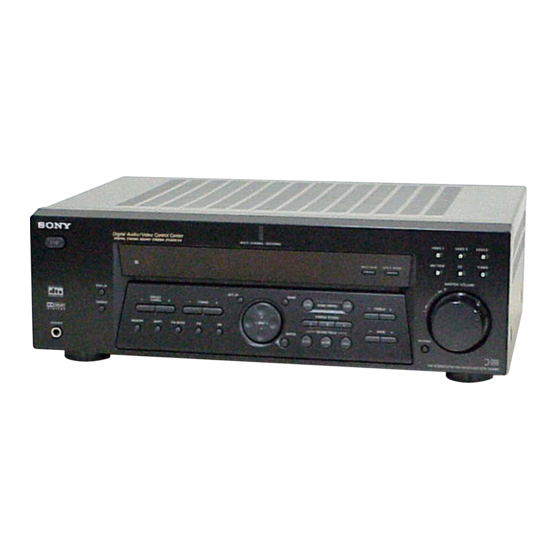
Sony STR-DE585 Service Manual
Fm stereo/fm-am receiver
Hide thumbs
Also See for STR-DE585:
- Operating instructions manual (61 pages) ,
- Limited warranty (1 page) ,
- Operating instructions manual (88 pages)
Table of Contents
Advertisement
SERVICE MANUAL
Ver 1.0 2002. 04
Manufactured under license from Dolby Laboratories.
"Dolby", "Pro Logic" and the double-D symbol are
trademarks of Dolby Laboratories.
"DTS" and "DTS Digital Surround" are registered
trademarks of Digital Theater Systems, Inc.
AUDIO POWER SPECIFICATIONS
Amplifier section
POWER OUTPUT
Models of area code Canadian
Rated Power Output at Stereo Mode
(8 ohms 40 Hz – 20 kHz, THD 0.09 %)
100 W + 100 W
Reference Power Output
(8 ohms 1 kHz, THD 0.7 %)
1)
FRONT
CENTER
SURR
1)
: 100 W/ch
Models of area code AEP, UK
Rated Power Output at Stereo Mode
(8 ohms 1 kHz, THD 0.7 %)
100 W + 100 W
Reference Power Output
(8 ohms 1 kHz, THD 0.7 %)
1)
FRONT
CENTER
1)
SURR
: 100 W/ch
1) Depending on the sound field settings and the
source, there may be no sound output.
2) Measured under the following conditions:
Area code
Power requirements
AEP, UK
230 V AC, 50 Hz
Sony Corporation
9-873-966-01
2002D0400-1
Home Audio Company
© 2002. 04
Published by Sony Engineering Corporation
SPECIFICATIONS
: 100 W/ch
1)
: 100 W
2)
: 100 W/ch
1)
: 100 W
STR-DE585
Frequency response
MULTI CH IN, CD,
10 Hz – 50 kHz
MD/TAPE, DVD/LD,
+0.5/–2 dB (with sound
VIDEO 1, 2
field, and tone bypassed)
Inputs (Analog)
MULTI CH IN, CD,
Sensitivity: 250 mV
MD/TAPE, DVD/LD,
Impedance: 50 kilohms
VIDEO 1, 2
S/N
(A, 250 mV
3) INPUT SHORT (with sound field and tone
bypassed).
4) Weighted network, input level.
Inputs (Digital)
DVD/LD (Coaxial)
Sensitivity: –
Impedance: 75 ohms
S/N: 100 dB
(A, 20 kHz LPF)
VIDEO 2 (Optical)
Sensitivity: –
Impedance: –
S/N: 100 dB
(A, 20 kHz LPF)
Outputs
MD/TAPE (REC
Voltage: 250 mV
OUT), VIDEO1
Impedance: 10 kilohms
(AUDIO OUT)
SUB WOOFER
Voltage: 2 V
Impedance: 1 kilohms
Tone
Gain levels:
±6 dB, 1 dB step
FM STEREO/FM-AM RECEIVER
Canadian Model
AEP Model
UK Model
3)
: 96 dB
4)
)
– Continued on next page –
1
Advertisement
Table of Contents

Related Manuals for Sony STR-DE585


Summary of Contents for Sony STR-DE585
- Page 1 230 V AC, 50 Hz Impedance: 1 kilohms Tone Gain levels: ±6 dB, 1 dB step – Continued on next page – FM STEREO/FM-AM RECEIVER Sony Corporation 9-873-966-01 2002D0400-1 Home Audio Company © 2002. 04 Published by Sony Engineering Corporation...
- Page 2 STR-DE585 FM tuner section Video section Tuning range 87.5 - 108.0 MHz Inputs Antenna terminals 75 ohms, unbalanced Video: 1 Vp-p, 75 ohms Intermediate Frequency 10.7 MHz Outputs Sensitivity Video: 1 Vp-p, 75 ohms Mono: 18.3 dBf, 2.2 µV/75 ohms...
- Page 3 CRITIQUES POUR LA SÉCURITÉ DE FONCTIONNEMENT. NE REPLACE THESE COMPONENTS WITH SONY PARTS WHOSE REMPLACER CES COMPOSANTS QUE PAR DES PIÈCES SONY PART NUMBERS APPEAR AS SHOWN IN THIS MANUAL OR DONT LES NUMÉROS SONT DONNÉS DANS CE MANUEL OU IN SUPPLEMENTS PUBLISHED BY SONY.
-
Page 4: Table Of Contents
STR-DE585 TABLE OF CONTENTS 1. GENERAL Main unit ................. 5 Remote button description ............6 2. DISASSEMBLY 2-1. Case ..................8 2-2. Front Panel Section ............. 9 2-3. Back Panel ................9 2-4. Digital Board ..............10 2-5. Standby Board ..............10 2-6. -
Page 5: General
STR-DE585 SECTION 1 GENERAL This section is extracted from instruction manual. List of Button Locations and Reference Pages Illustration number How to use this page NAME 8 (35) Use this page to find the location of buttons that are mentioned in the text. -
Page 6: Remote Button Description
STR-DE585 Operations Using the Remote RM-PP506 Remote Operations Function Button You can use the remote RM-PP506 to operate the components in your system. VIDEO 1 Receiver To watch VCR. (VTR mode 3) VIDEO 2 Receiver To watch VCR. (VTR mode 1) - Page 7 STR-DE585 Operations Using the Remote RM-U306 Except for STR-DE585 area code CA Remote button description (continued) You can use the remote RM-U306 to operate the components in your system. Remote Operations Function Button Remote button VIDEO 1 Receiver To watch VCR.
-
Page 8: Disassembly
STR-DE585 SECTION 2 DISASSEMBLY Note : This set can be disassemble according to the following sequence. 2-1. CASE (Page 8) 2-2. FRONT PANEL SECTION 2-3. BACK PANEL (Page 9) (Page 9) 2-4. DIGITAL BOARD (Page 10) 2-5. STANDBY BOARD (Page 10) 2-6. -
Page 9: Front Panel Section
STR-DE585 2-2. FRONT PANEL SECTION 3 two screws (BVTP3 x 8) 2 CNP791 5 front panel section 1 CNS4 4 four screws (BVTP3 x 8) 2-3. BACK PANEL qd back panel (DE4)(Canadian) back panel (DE5)(AEP, UK) 0 screw (BVTP3 x 8) -
Page 10: Digital Board
STR-DE585 2-4. DIGITAL BOARD 7 DIGITAL board 2 CNP6 3 CNP5 8 screw (BVTP3 x 8) 6 CNS2 5 CNS1 9 bracket (digital) 4 screw (BVTP3 x 8) 1 CNS4 2-5. STANDBY BOARD 4 three screws (BVTP3 x 8) 2 CNP902... -
Page 11: Main Board
STR-DE585 2-6. MAIN BOARD 1 CNP801 7 MAIN board 5 screw 2 CNP802 (BVTP3 x 8) 4 two screws (BVTP3 x 6) 3 two screws 6 two screws (BVTP3 x 6) (BVTP3 x 8) -
Page 12: Test Mode
STR-DE585 SECTION 3 TEST MODE SOFTWARE VERSION DISPLAY MODE FACTORY PRESET MODE * The software version is displayed. * All preset contents are reset to the default setting. * Procedure: * Procedure: While depressing the [ENTER] and the SOUND FIELD [A.DEC]... -
Page 13: Diagrams
STR-DE585 SECTION 4 DIAGRAMS 4-1. IC PIN DESCRIPTIONS • IC1201 CXD9617R (DSP) (DIGITAL Board (1/2)) Pin No. Pin Name Description — Ground XRST Reset signal input EXTIN Not used (connected to ground) Not used (connected to ground) VDDI Power supply... - Page 14 STR-DE585 Pin No. Pin Name Description BOOT Not used (connected to ground) BTACT Not used (open) Boot stop signal input MOD1 Operation mode signal input (L : 386fs, H : 256fs) MOD0 Operation mode signal input (L : single chip mode, H : use prohibited)
- Page 15 STR-DE585 • IC1601 MB90478PF-G-120-BND (SYSTEM CONTROL) (DIGITAL Board (2/2)) Pin No. Pin Name Description Pin No. Pin Name Description DATAO Serial data input for DIR POWER KEY Detect power switch key Decode signal input JOG (B) Jog encoder signal input (Fixed at “L”)
-
Page 16: Block Diagram - Tuner/Audio Section
STR-DE585 4-2. BLOCK DIAGRAM — TUNER/AUDIO SECTION — FUNCTION SELECT TM301 IC201 FM/AM TUNER UNIT J402 (2/2) TU+10V R-CH +10V MD/TAPE IN 8 LREC 3 L CH FM 75Ω COAXIAL R CH R-CH J402 (1/2) J404 (2/2) ANTENNA IN 9... -
Page 17: Block Diagram - Digital Section
STR-DE585 4-3. BLOCK DIAGRAM — DIGITAL SECTION — CODEC IC1501 IC1201 L IN- AUDIO SDTO SDTI1 LOUT1 DSI1 SD01 DLIN L IN+ L-IN (1/2) TUNER/ SDTI2 SD02 24 AUDIO LOUT 3 AUDIO DCIN SECTION SDTI3 TUNER/ SD03 25 (2/2) R-IN... -
Page 18: Block Diagram - Video/Display Section
STR-DE585 4-4. BLOCK DIAGRAM — VIDEO/DISPLAY SECTION — VIDEO SELECTOR IC103 J201 (1/2) VIDEO VIDEO 1 J201 (2/2) M.OUT J200 (1/2) VIDEO MONITOR VIDEO VIDEO 2 J200 (2/2) V1.OUT VIDEO VIDEO VIDEO 1 DVD/LD IC807 FL101 FLUORESCENT INDICATOR IC804 TUBE... -
Page 19: Block Diagram - Power Section
STR-DE585 4-5. BLOCK DIAGRAM — POWER SECTION — J791 PHONES PRE DRIVER R-CH IC701 TM602 +VOUT2 IN 2 DRIVE -VOUT2 FL-CH DRIVE POWER AMP Q701-704 RELAY FR-CH R-CH CURRENT OVERLOAD DRIVER FRONT R-CH Q790 DETECT DETECT -BB +B RY791 Q705,706... -
Page 20: Circuit Boards Location
STR-DE585 4-6. CIRCUIT BOARDS LOCATION THIS NOTE IS COMMON FOR PRINTED WIRING BOARDS AND SCHEMATIC DIAGRAMS. (In addition to this, the necessary note is printed in each block.) STANDBY board for schematic diagram: for printed wiring boards: • All capacitors are in µF unless otherwise noted. pF: µµF •... -
Page 21: Printed Wiring Boards - Main Section
STR-DE585 4-7. PRINTED WIRING BOARDS — MAIN SECTION — • Refer to page 20 for Common Note on Printed Wiring Boards and Circuit Boards Location. TM601 TM602 J401 J402 J403 J404 J405 (Page 28) CC18 CC19 CC41 CC31 R411 R435... -
Page 22: Schematic Diagram - Main Section (1/2)
STR-DE585 4-8. SCHEMATIC DIAGRAM — MAIN SECTION (1/2) — • Refer to page 20 for Common Note on Schematic Diagram. C481 C491 C493 C483 J404 R407 CC07 C407 R427 R447 CC57 R457 C457 C492 R373 C500 CC06 R406 Q361 C406... -
Page 23: Schematic Diagram - Main Section (2/2)
STR-DE585 4-9. SCHEMATIC DIAGRAM — MAIN SECTION (2/2) — • Refer to page 20 for Common Note on Schematic Diagram and page 34 for IC Block Diagrams. CNP791 Q747 CN792 C792 C790 R792 RY791 IC B/D R723 J791 C717 R719... -
Page 24: Printed Wiring Board - Digital Section (1/2)
STR-DE585 4-10. PRINTED WIRING BOARD — DIGITAL SECTION (1/2) — • Refer to page 20 for Common Note on Printed Wiring Boards and Circuit Boards Location. • Semiconductor Location (side A) Ref. No. Location D1001 G-10 D1101 F-10 D1601 L1901... -
Page 25: Printed Wiring Board - Digital Section (2/2)
STR-DE585 4-11. PRINTED WIRING BOARD — DIGITAL SECTION (2/2) — • Refer to page 20 for Common Note on Printed Wiring Boards and Circuit Boards Location. TM301 • Semiconductor (Page 32) (Page 21) (Page 28) Location (side B) Ref. No. -
Page 26: Schematic Diagram - Digital Section (1/2)
STR-DE585 4-12. SCHEMATIC DIAGRAM — DIGITAL SECTION (1/2) — • Refer to page 20 for Common Note on Schematic Diagram and Waveforms, and refer to page 34 for IC Block Diagrams. C1129 C1111 FB1102 C1112 (Page 27) R1115 IC B/D... -
Page 27: Schematic Diagram - Digital Section (2/2)
STR-DE585 4-13. SCHEMATIC DIAGRAM — DIGITAL SECTION (2/2) — • Refer to page 20 for Common Note on Schematic Diagram and Waveforms. CNP5 (Page 33) R1688 CNP6 D1907 IC1904 L1901 IC1903 D1906 D1905 IC1901 (Page 22) C1908 C1906 C1912 C1910... -
Page 28: Printed Wiring Board - Video Section
STR-DE585 4-14. PRINTED WIRING BOARD — VIDEO SECTION — • Refer to page 20 for Common Note on Printed Wiring Boards and Circuit Boards Location. • Semiconductor Location Ref. No. Location D203 D204 IC103 IC804 E-10 IC807 C-11 (Page 25) -
Page 29: Schematic Diagram - Video Section
STR-DE585 4-15. SCHEMATIC DIAGRAM — VIDEO SECTION — • Refer to page 20 for Common Note on Schematic Diagram and page 34 for IC Block Diagrams. R201 J201 C208 R219 C214 C201 R220 C210 C209 C200 J200 R200 IC B/D... -
Page 30: Printed Wiring Boards - Display Section
STR-DE585 4-16. PRINTED WIRING BOARDS — DISPLAY SECTION — • Refer to page 20 for Common Note on Printed Wiring Boards and Circuit Boards Location. D102 S131 S116 S108 D100 JW111 R132 C151 C115 C114 R116 C156 R153 R114 CNP103... -
Page 31: Schematic Diagram - Display Section
STR-DE585 4-17. SCHEMATIC DIAGRAM — DISPLAY SECTION — • Refer to page 20 for Common Note on Schematic Diagram. R101 R102 R103 R104 R105 R106 R107 R108 R109 S100 S101 S102 S103 S104 S105 S106 S107 S108 S109 Q111 R175... -
Page 32: Printed Wiring Board - Power Section
STR-DE585 4-18. PRINTED WIRING BOARD — POWER SECTION — • Refer to page 20 for Common Note on Printed Wiring Boards and Circuit Boards Location. • Semiconductor Location Ref. No. Location D820 D821 D822 D823 D898 (Page 21) D899 D901... -
Page 33: Schematic Diagram - Power Section
STR-DE585 4-19. SCHEMATIC DIAGRAM — POWER SECTION — • Refer to page 20 for Common Note on Schematic Diagram. T901 (Page 22) (Page 22) CNP903 CNP902 CNP905 R810 D820 D823 C815 F901 Q901 R812 C813 C816 D822 D821 R811 R903... -
Page 34: Ic Block Diagrams
STR-DE585 4-20. IC BLOCK DIAGRAMS IC501 STK350-230 (MAIN BOARD (2/2)) IC1501 AK4527 (DIGITAL BOARD (1/2)) DRIVER AUDIO MCLK 33 DZF2 7 8 9 32 RIN+ SDOS SDOUT 31 RIN- 30 LIN+ FORMAT 29 LIN- CONVERTER S.MUTE BCLK DATT 28 ROUT1... -
Page 35: Exploded Views
STR-DE585 SECTION 5 EXPLODED VIEWS NOTE: • The mechanical parts with no reference • Color Indication of Appearance Parts The components identified by mark 0 or dotted line with mark number in the exploded views are not supplied. Example : 0 are critical for safety. -
Page 36: Front Panel Section
STR-DE585 5-2. FRONT PANEL SECTION supplied with RV102 Ref. No. Part No. Description Remark Ref. No. Part No. Description Remark X-4954-472-1 PANEL ASSY, FRONT (BLACK) (Canadian) 1-683-759-11 POWER SW BOARD X-4954-706-1 PANEL ASSY, FRONT (BLACK) (AEP,UK) 4-951-620-01 SCREW (2.6X8), +BVTP... -
Page 37: Chassis Section-1
STR-DE585 5-3. CHASSIS SECTION-1 not supplied TM301 not supplied not supplied The components identified by Les composants identifiés par une mark 0 or dotted line with mark marque 0 sont critiques pour la 0 are critical for safety. sécurité. Replace only with part number Ne les remplacer que par une piéce... -
Page 38: Chassis Section-2
STR-DE585 5-4. CHASSIS SECTION-2 Q603 Q604 Q754 Q753 Q654 Q653 Q704 Q703 Q504 Q503 F901 not supplied not supplied T901 not supplied The components identified by Les composants identifiés par une mark 0 or dotted line with mark marque 0 sont critiques pour la 0 are critical for safety. -
Page 39: Electrical Parts List
STR-DE585 SECTION 6 DIGITAL ELECTRICAL PARTS LIST NOTE: • Due to standardization, replacements in • Items marked “*” are not stocked since The components identified by mark 0 or dotted line with mark the parts list may be different from the they are seldom required for routine service. - Page 40 STR-DE585 DIGITAL Ref. No. Part No. Description Remark Ref. No. Part No. Description Remark C1611 1-162-974-11 CERAMIC CHIP 0.01uF FB1104 1-469-152-11 FERRITE, EMI (SMD) C1612 1-164-156-11 CERAMIC CHIP 0.1uF FB1105 1-469-152-11 FERRITE, EMI (SMD) C1613 1-162-995-11 CERAMIC CHIP 0.022uF FB1201 1-414-813-11 FERRITE, EMI (SMD)
- Page 41 STR-DE585 DIGITAL Ref. No. Part No. Description Remark Ref. No. Part No. Description Remark Q1602 8-729-230-49 TRANSISTOR 2SC2712-YG R1505 1-216-825-11 METAL CHIP 2.2K 1/10W R1506 1-216-833-11 METAL CHIP 1/10W < RESISTOR > R1507 1-216-829-11 METAL CHIP 4.7K 1/10W R1508 1-216-845-11 METAL CHIP...
-
Page 42: Digital Display
STR-DE585 DIGITAL DISPLAY Ref. No. Part No. Description Remark Ref. No. Part No. Description Remark R1639 1-216-809-11 METAL CHIP 1/10W R1707 1-216-833-11 METAL CHIP 1/10W R1640 1-216-809-11 METAL CHIP 1/10W R1708 1-216-833-11 METAL CHIP 1/10W R1641 1-216-809-11 METAL CHIP 1/10W... - Page 43 STR-DE585 DISPLAY Ref. No. Part No. Description Remark Ref. No. Part No. Description Remark < DIODE > R119 1-249-437-11 CARBON 1/4W R121 1-249-413-11 CARBON 1/4W D100 8-719-075-59 LED SELS5B23C-TP15 (Digital Cinema Sound) R122 1-249-417-11 CARBON 1/4W D102 8-719-084-07 LED SEL5E20C-TP15...
- Page 44 STR-DE585 DISPLAY HEADPHONE MAIN Ref. No. Part No. Description Remark Ref. No. Part No. Description Remark S107 1-771-410-21 SWITCH, TACTILE (SET UP) A-4676-978-A MAIN BOARD, COMPLETE (AEP,UK) S108 1-771-410-21 SWITCH, TACTILE (VIDEO 1) A-4727-992-A MAIN BOARD, COMPLETE (Canadian) S109 1-771-410-21 SWITCH, TACTILE (MD/TAPE)
- Page 45 STR-DE585 MAIN Ref. No. Part No. Description Remark Ref. No. Part No. Description Remark C489 1-128-809-11 CERAMIC 100PF C703 1-104-665-11 ELECT 100uF C490 1-128-809-11 CERAMIC 100PF C704 1-107-583-11 CERAMIC 0.25PF 500V C491 1-126-964-11 ELECT 10uF C705 1-102-233-00 CERAMIC 33PF 500V...
- Page 46 STR-DE585 MAIN Ref. No. Part No. Description Remark Ref. No. Part No. Description Remark CC08 1-128-809-11 CERAMIC 100PF D690 8-719-934-21 DIODE HZS30-1L (AEP,UK) D691 8-719-991-33 DIODE 1SS133T-77 CC09 1-128-809-11 CERAMIC 100PF D705 8-719-991-33 DIODE 1SS133T-77 (AEP,UK) D710 8-719-991-33 DIODE 1SS133T-77...
- Page 47 STR-DE585 MAIN Ref. No. Part No. Description Remark Ref. No. Part No. Description Remark Q379 8-729-900-63 TRANSISTOR DTA124ES R376 1-249-417-11 CARBON 1/4W Q471 8-729-823-22 TRANSISTOR 2SC3576 R377 1-249-417-11 CARBON 1/4W Q501 8-729-119-76 TRANSISTOR 2SA1175-HFE R378 1-249-417-11 CARBON 1/4W Q502 8-729-141-30 TRANSISTOR 2SC3623A-LK...
- Page 48 STR-DE585 MAIN Ref. No. Part No. Description Remark Ref. No. Part No. Description Remark R499 1-249-437-11 CARBON 1/4W R653 1-249-414-11 CARBON 1/4W R501 1-249-417-11 CARBON 1/4W R654 1-249-439-11 CARBON 1/4W R502 1-249-439-11 CARBON 1/4W R655 1-249-433-11 CARBON 1/4W R503 1-249-414-11 CARBON...
- Page 49 STR-DE585 MAIN POWER SW STANDBY Ref. No. Part No. Description Remark Ref. No. Part No. Description Remark R736 1-249-417-11 CARBON 1/4W < RELAY > R737 1-249-436-11 CARBON 1/4W R740 1-249-433-11 CARBON 1/4W RY501 1-755-421-11 RELAY (12V) R742 1-249-437-11 CARBON 1/4W...
- Page 50 STR-DE585 STANDBY VIDEO Ref. No. Part No. Description Remark Ref. No. Part No. Description Remark D822 8-719-200-82 DIODE 11ES2 C248 1-128-825-21 CERAMIC 0.0022uF 5% D823 8-719-200-82 DIODE 11ES2 C249 1-128-825-21 CERAMIC 0.0022uF 5% D898 8-719-200-82 DIODE 11ES2 C809 1-126-947-11 ELECT...
- Page 51 STR-DE585 Ref. No. Part No. Description Remark MISCELLANEOUS *************** 1-773-250-11 WIRE (FLAT TYPE) (27 CORE) 1-769-940-11 WIRE (FLAT TYPE) (11 CORE) (Canadian) 1-773-004-11 WIRE (FLAT TYPE) (15 CORE) (AEP,UK) 1-575-662-31 WIRE (FLAT TYPE) (5 CORE) 0 105 1-769-744-11 CORD, POWER (AEP,UK)
- Page 52 STR-DE585 REVISION HISTORY Clicking the version allows you to jump to the revised page. Also, clicking the version at the upper on the revised page allows you to jump to the next revised page. Ver. Date Description of Revision 2002. 04...
Need help?
Do you have a question about the STR-DE585 and is the answer not in the manual?
Questions and answers